
Low-leakage valve apparatus

a valve and low-leakage technology, applied in the field of stem valves, can solve the problems of increasing the compression, affecting the sealing effect of the valve stem, and the immediate isolation of the valve from the process, so as to reduce the packing pressure and increase or decrease the compression of the packing

Active Publication Date: 2006-05-23
WESTERN REFINING SOUTHWEST
View PDF20 Cites 8 Cited by
  • Summary
  • Abstract
  • Description
  • Claims
  • Application Information

AI Technical Summary

Benefits of technology

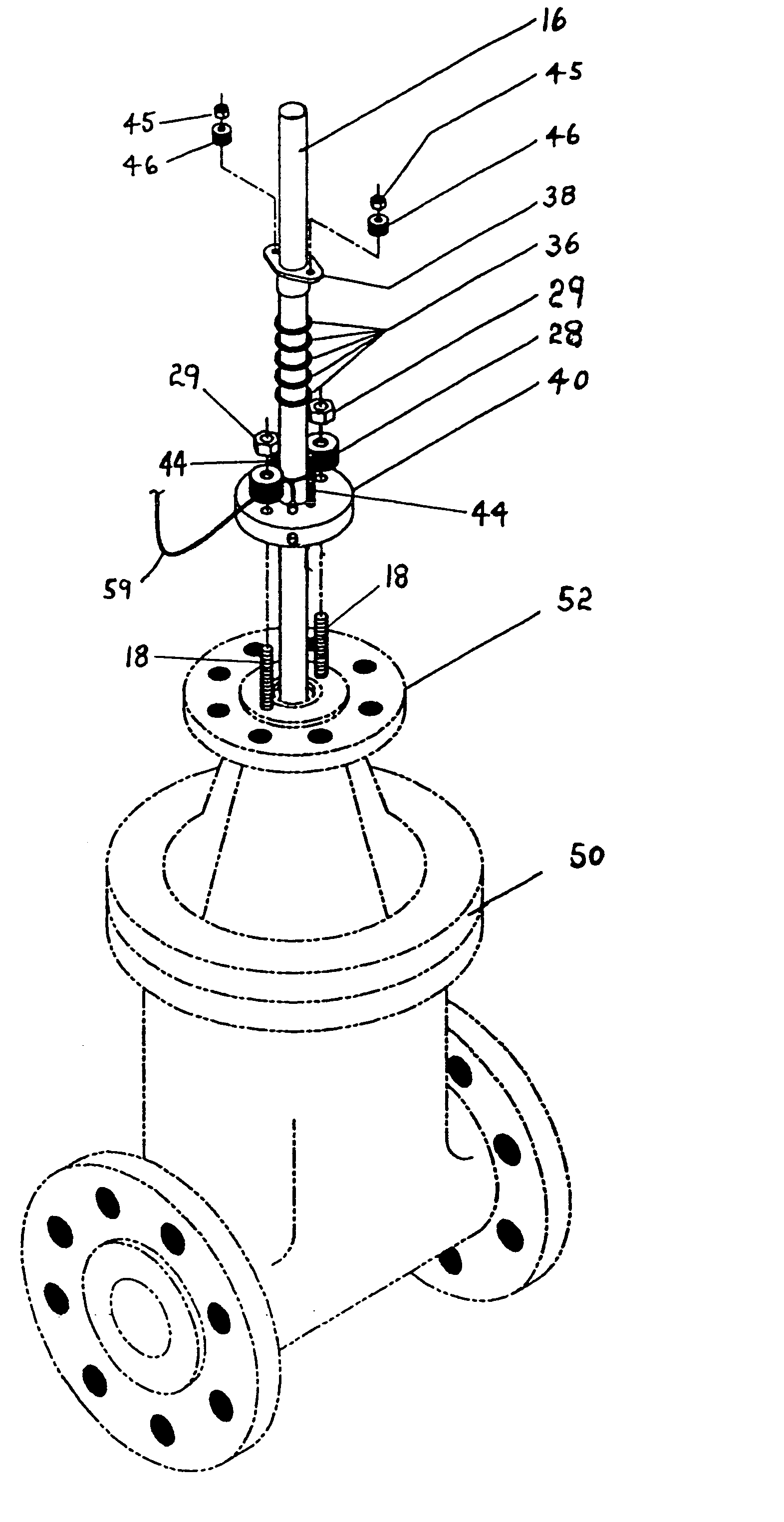
[0020]A primary advantage of the present invention is that it can be economically retro-fitted onto existing valves.
[0021]Another advantage of the invention is that it provides a second packing chamber, or stuffing box, the compression of whose packing can be increased or decreased independently of the compression applied to the valve's primary packing.
[0022]Another advantage of the invention is that the secondary packing chamber of the apparatus is exposed to a reduced driving force or pressure, permitting the packing to be subjected to lower packing pressure, thereby extending the life of the apparatus as a useful adjunct to an existing valve.
[0023]Yet another advantage of the invention is that it provides a second compartment, outside and independent of the primary packing and the operating pressures that may exist there, in which to collect any leakage past the primary packing chamber.

Problems solved by technology

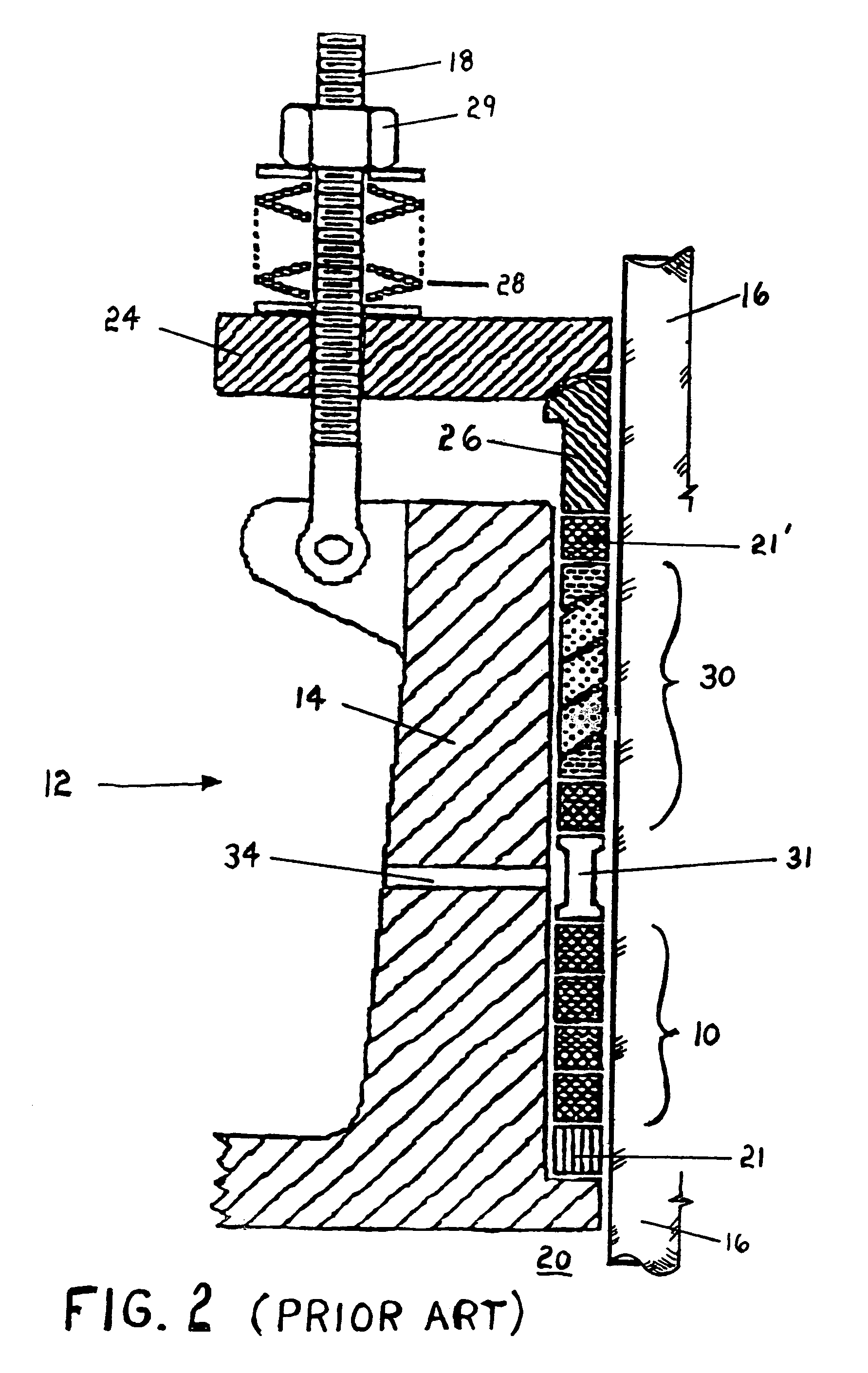
This temporary solution often eventually results in the compression being increased to the point that it is difficult for the valve stem 16 to move smoothly past the packing.
Another problem which may occur, and is more severe, is the failure of the packing 10 or 30 due to over-compression, which may result in a large atmospheric release of process fluid from the valve, forcing immediate isolation of the valve from the process.
Fugitive emissions from valves are an undesirable occurrence in many industries.
Known devices, however, may be compromised by various drawbacks.
This often results in the need for high compression on the packings, which can be counter productive especially in high-use valves.
Many devices compress simultaneously all the packings in the primary packing chamber, unnecessarily subjecting all packings—which are intended to retain fluid against the system operating pressure—to higher rates of wear.

Method used


Image

  • Low-leakage valve apparatus
  • Low-leakage valve apparatus
  • Low-leakage valve apparatus

Examples


example 1

[0062]An apparatus was designed and assembled generally in accordance with the foregoing disclosure, and installed upon 8-inch and 10-inch actuated gate valves in a fluid stream within a process system at a crude oil refinery. Such valves, as with many valves in complex industrial processes, cycle from the fully open position to the fully closed position tens of thousands of times annually. Reference is made to FIG. 7, tabulating the testing of VOC emissions to the atmosphere in the present example. A series of tests were conducted, two series on the valves prior to the installation of the apparatus, and two series on the same valves after apparatus installation. In all series, the concentration of fugitive VOC emissions to the atmosphere was measured at the valve using accepted Environmental Protection Agency testing procedures. Emissions were in excess of 10,000 ppm for all pre-installation tests, as seen in the table of FIG. 7. Post-installation tests indicated dramatic reduction...


PUM


Abstract

A low-leakage valve apparatus which reduces fugitive emissions from valves to the ambient atmosphere. A secondary packing chamber or gland is installed on an existing valve to intercept leakage past the valve's original primary packing gland, which otherwise would escape past the valve stem to the atmosphere.

Description

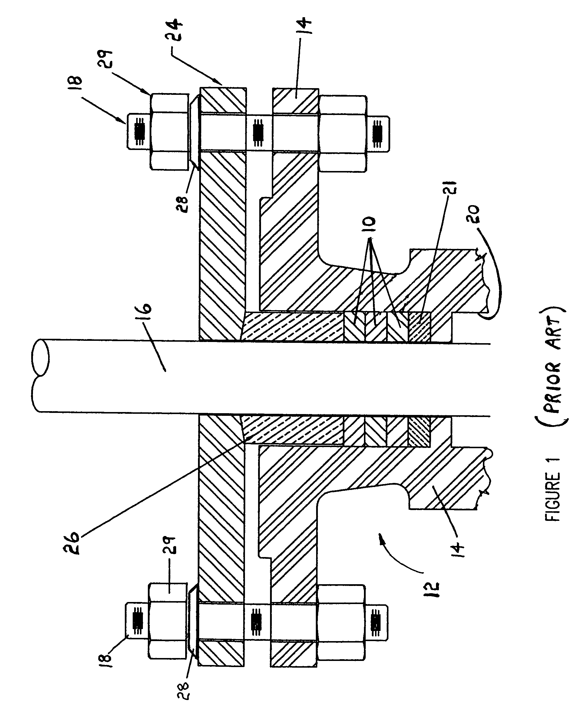
BACKGROUND OF THE INVENTION[0001]1. Field of the Invention (Technical Field)[0002]The present invention relates to valves, particularly to stem valves, an specifically to a valve having a sealed stem to significantly reduce or minimize liquid / gas / vapor leakage.[0003]2. Background Art[0004]Conventional stem valves feature a movable stem. A valve stem may have a rotating and / or sliding movement within its sleeve throughout the valve's distance of travel; the sealing of the stem must be sufficient to contend with that movement while also maintaining fluid tightness against the pressure of the fluid in the valve.[0005]A widely used type of stem sealing (see FIG. 1, prior art) is accomplished by compressing packing 10 in a gland or stuffing box 12, which may be integral to the valve body 14, or bolted to the valve body. “Packing” is any of a wide variety of compressible materials known in the art (in early valves oakum was used) for providing a seal through which the valve stem 16 can sl...

Claims


Application Information

Patent Timeline
IPC IPC(8): F16K31/44F16K41/02F16K43/00
CPCF16K43/00F16K41/02
Inventor LAURENT, JOHN ARTHURHALLOCK, JAMES PATRICK
Owner WESTERN REFINING SOUTHWEST
Learn More