Eureka AIR delivers breakthrough ideas for toughest innovation challenges, trusted by R&D personnel around the world.

Catheter with electrode strip

a catheter and electrode technology, applied in the field of catheters with electrode strips, can solve the problems of strip damage, substantial deformation of elastic materials, loss of electrical contact with electrodes, etc., and achieve the effect of reducing the tensile and shear forces exerted on the electrode strips and attaching an array of electrodes to the probes. simple and economically

Inactive Publication Date: 2005-02-10
BIOSENSE WEBSTER INC
View PDF5 Cites 130 Cited by
  • Summary
  • Abstract
  • Description
  • Claims
  • Application Information

AI Technical Summary

Benefits of technology

[0007] The use of the electrode strip in this manner makes it possible to attach an array of electrodes to the probe simply and economically, without the need to create multiple holes in the probe or to run a wire to each electrode, as in devices known in the art. In embodiments of the present invention, only a single hole is typically made in the probe, for connecting the conductors at the proximal end of the electrode strip to the wires or circuits inside the probe.
[0008] Typically, the distal portion of the probe is bendable, generally for purposes of steering the probe inside the body. Bending the catheter can exert tensile and shear forces on the strip at the outside of the bend. Since the electrodes and conductors on the electrode strip are generally inelastic, these tensile forces could cause damage to the strip, such as loss of electrical contact with the electrodes. To avoid this problem, in some embodiments of the present invention, at least the distal portion of the probe comprises a relatively soft, elastic material, while the substrate of the electrode strip is strong and substantially inelastic. When the probe bends, the pressure exerted on the probe by the electrode strip at the outside of the bend causes substantial deformation of the elastic material. The tensile and shear forces exerted on the electrode strip are thus substantially reduced.

Problems solved by technology

Since the electrodes and conductors on the electrode strip are generally inelastic, these tensile forces could cause damage to the strip, such as loss of electrical contact with the electrodes.
When the probe bends, the pressure exerted on the probe by the electrode strip at the outside of the bend causes substantial deformation of the elastic material.

Method used


Image

  • Catheter with electrode strip
  • Catheter with electrode strip
  • Catheter with electrode strip

Examples


Embodiment Construction

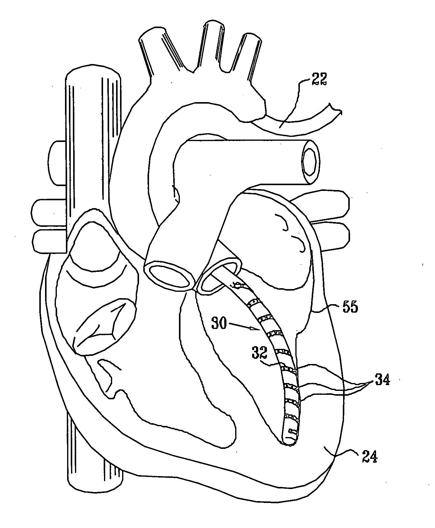
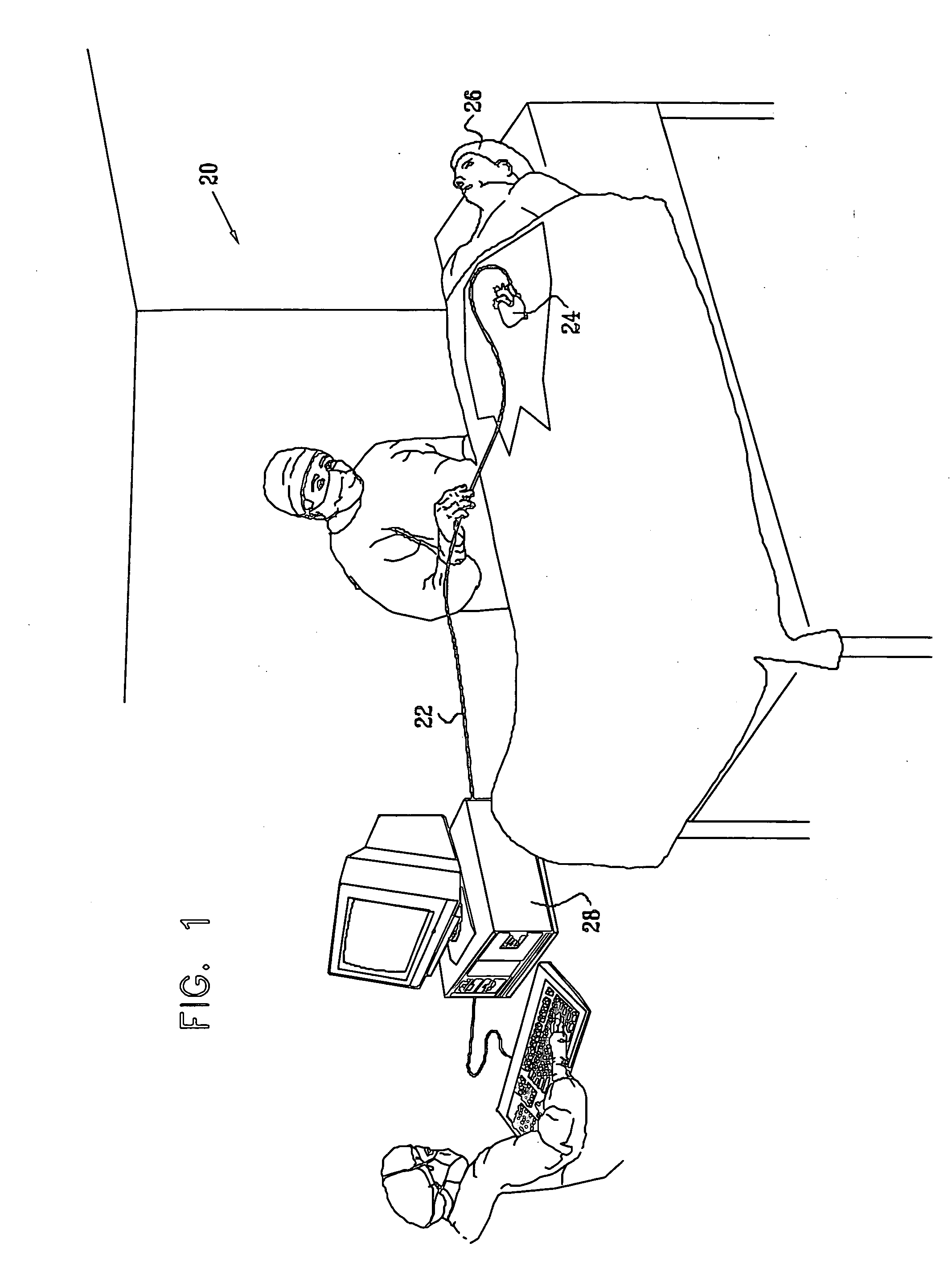
[0037]FIG. 1 is a schematic, pictorial illustration of a cardiac catheterization system 20, in accordance with an embodiment of the present invention. System 20 comprises an elongate probe, typically a catheter 22, which is inserted by a user through a vein or artery of a human or other mammalian subject 26 into a chamber of a heart 24 of the subject. Catheter 22 is coupled at its proximal end to a console 28, which receives electrical signals from electrodes fixed to the distal end of the catheter inside the heart, as described hereinbelow. The console may use these signals to create a map of electrical activity in the heart, as is known in the art. Alternatively or additionally, the console may be configured to provide electrical energy, typically RF energy, to the electrodes in order to ablate areas of the endocardium, as is likewise known in the art.

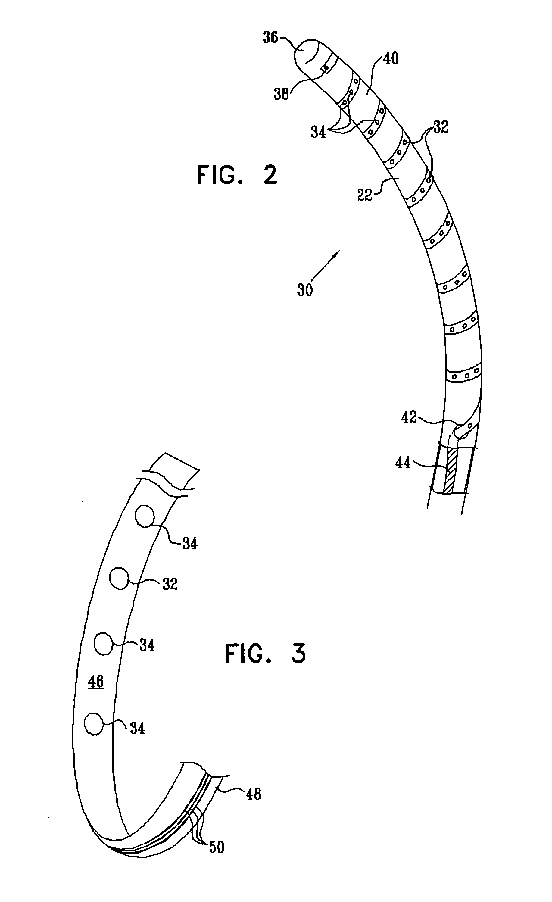
[0038]FIG. 2 is a schematic side view of a distal portion 30 of catheter 22, in accordance with an embodiment of the present inven...


PUM


Abstract

Apparatus for medical treatment or diagnosis in a body cavity of a mammalian subject includes an elongate probe, having an outer surface and comprising a distal portion, which is adapted for insertion into the body cavity. An electrode strip includes an elongate insulating substrate, which is wrapped around the distal portion of the probe so as to define a helix having distal and proximal ends and a length therebetween, the substrate being fixed to the outer surface of the probe over substantially all of the length of the helix. A plurality of electrodes are disposed along the length of the helix and fixed to the substrate. Electrical conductors are coupled to the electrodes and run along the substrate over the length of the helix so as to communicate with circuitry in a location proximal to the distal portion of the probe.

Description

FIELD OF THE INVENTION [0001] The present invention relates generally to invasive medical devices, and specifically to devices for mapping electrical activity in the heart. BACKGROUND OF THE INVENTION [0002] Catheters with electrode arrays on their outer surfaces are known in the art. For example, U.S. Pat. No. 6,063,022, whose disclosure is incorporated herein by reference, describes a catheter with an array of electrophysiological sensing electrodes spaced along its length. The catheter also comprises position sensors, for use in determining the location of the electrodes within the body. The electrodes and position sensors can thus be used to generate a map of physiological activity as a function of position within the body cavity. In another embodiment described in this patent, the catheter comprises an array of radio frequency (RF) ablation electrodes. [0003] Typically, in order to produce an electrode array on the catheter, a set of wires is threaded through a lumen of the dis...

Claims


Application Information

Patent Timeline
IPC IPC(8): A61B1/012A61B5/296A61B18/14A61N1/05
CPCA61B5/0422A61B18/1492A61B2017/003A61B2018/1435A61N1/056A61B2562/0209A61B2562/043A61N1/05A61B2018/1467A61B5/287A61B1/012
Inventor GOVARI, ASSAFALTMANN, ANDRES CLAUDIO
Owner BIOSENSE WEBSTER INC
Why Eureka
Eureka Blog
Learn More