Driving device

Inactive Publication Date: 2006-05-23
ATLAS COPCO ELECTRIC TOOLS
View PDF20 Cites 53 Cited by
  • Summary
  • Abstract
  • Description
  • Claims
  • Application Information

AI Technical Summary

Benefits of technology

[0012]Advantageously, the driven member is force-lockingly connected to the spindle. This can be achieved by a press fit, for example. Thereby, a slip-clutch-lik

Problems solved by technology

The torque-transmitting surfaces of the cams and the driven member are designed to be very small in this solution and they are, therefore, subject to wear.

Method used


Image

  • Driving device
  • Driving device
  • Driving device

Examples


Embodiment Construction

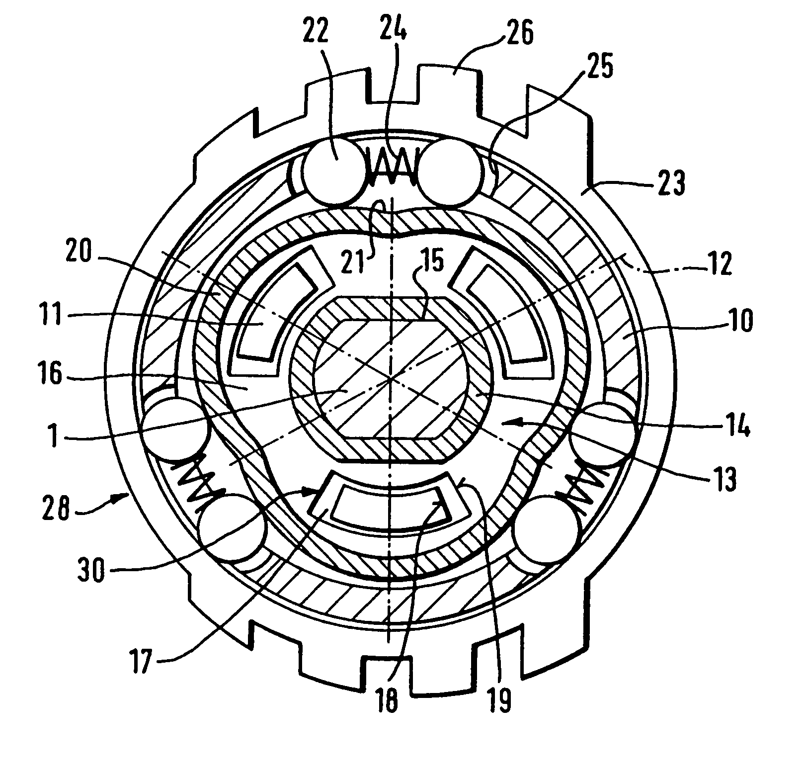
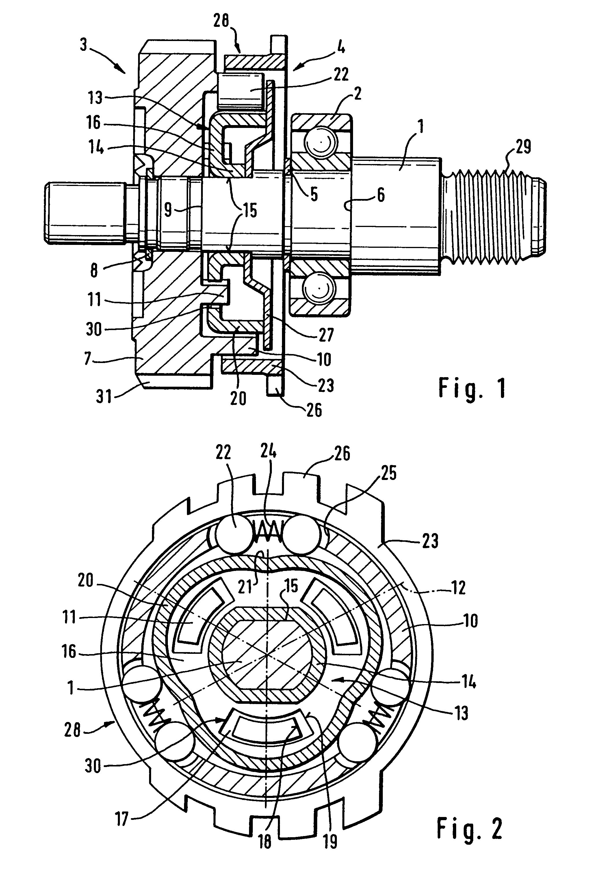
[0020]FIGS. 1 and 2 show a spindle 1 with a thread 29 for the drill chuck and a ball bearing 2 as well as a drive member 3 and a driven member 4.

[0021]The interior ring of the ball bearing 2 is axially supported on a shoulder 6 of the spindle 1 by a locking ring 5. A second bearing provided at the driving end of the spindle 1 is not illustrated.

[0022]The driving member 3 consists of a toothed wheel 7 that has an end gearing and is supported on the spindle 1. The toothed wheel 7 is axially fixed with axial play by a further locking ring 8 and a shoulder 9 of the spindle 1. For noise-related reasons, the gearing can be comprised of plastic. At the end face of the toothed wheel 7 facing the driven member 4, three unlocking members 10 and three axial cams 11 are arranged in pairs concentrically with respect to one another. The three pairs each have a common center line 12, and neighboring center lines 12 are provided at equal spacings.

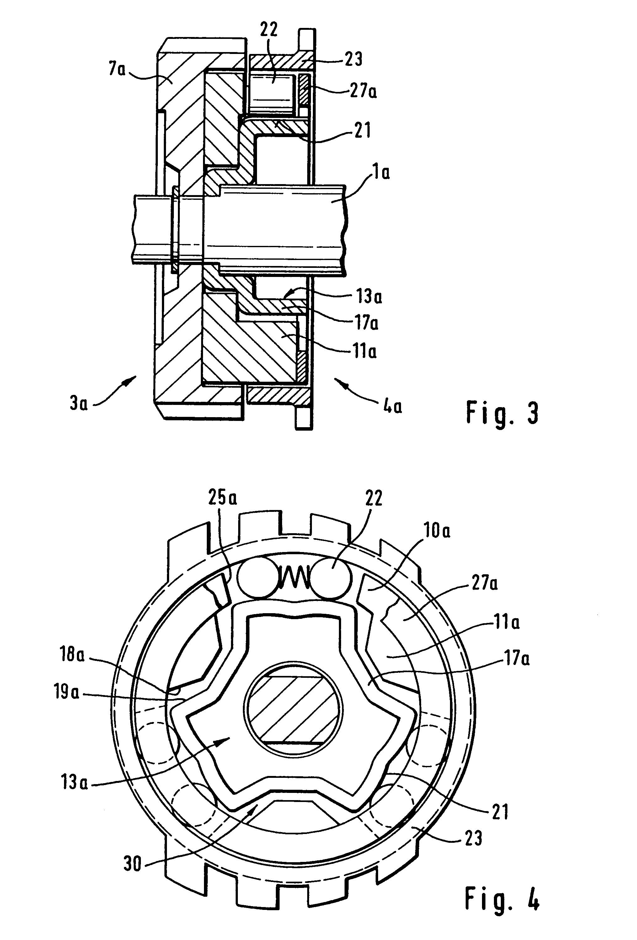
[0023]The driving member 3 can also be embodied as a...


PUM

PropertyMeasurementUnit
Distanceaaaaaaaaaa

Abstract

A shaft locking device for a motor-driven, hand-guided work tool spindle has a driven member fixedly connected thereto, a freewheel with locking members, a ring fixedly connected to the housing and engaged by the locking members in both rotating directions, a drive member coaxially arranged to the spindle with unlocking members cooperating with locking members releasing when the driving member is engaged, thereby releasing the driven member from the ring. Drive member cams are spatially separated from unlocking members wherein they penetrate the locking member. Driven members have catch openings such that both drive and driven members also have torque-transmitting catch surfaces for a motor-driven action of the spindle so that the catch surfaces have a larger distance from one another in a neutral position of the drive member than between the unlocking members and the locking members.

Description

BACKGROUND OF THE INVENTION[0001]The invention relates to a shaft locking device for the spindle of a motor-driven, hand-guided work tool.[0002]A shaft locking device of the aforementioned kind is described in U.S. Pat. No. 3,243,023 which comprises a drive member with four unlocking elements for the locking members of a freewheel and where the unlocking elements are simultaneously designed as cams for engaging a driven member. The torque-transmitting surfaces of the cams and the driven member are designed to be very small in this solution and they are, therefore, subject to wear.[0003]It is an object of the invention to create a shaft locking device for the spindle of a motor-driven, hand-held work tool that has a long service life.SUMMARY OF THE INVENTION[0004]Due to the spacial separation of unlocking elements and cams, there is space for sufficiently dimensioned torque-transmitting drive surfaces which are practically not subject to any wear.[0005]Because of the one-piece design...

Claims


Application Information

Patent Timeline
IPC IPC(8): F16D41/10B60N2/22B23B45/16B25F5/00
CPCF16D41/105B25F5/001
Inventor GEIS, WILHELMMENRATH, MANUELA
Owner ATLAS COPCO ELECTRIC TOOLS
Why Eureka
Try Eureka