Eureka AIR delivers breakthrough ideas for toughest innovation challenges, trusted by R&D personnel around the world.

System and method of vehicle surveillance

a vehicle and surveillance technology, applied in the field of vehicle surveillance, can solve the problems of draining our law enforcement system, insurance companies, and other economic resources, professional and non-professional thieves commit vehicle theft, and motor vehicle theft is the most expensive property crim

Inactive Publication Date: 2006-05-16
ENDEAVORING LLC
View PDF3 Cites 91 Cited by
  • Summary
  • Abstract
  • Description
  • Claims
  • Application Information

AI Technical Summary

Problems solved by technology

Even without factoring in the cost of higher insurance rates, the victim's loss of productivity, the impact on legitimate auto parts vendors, manufacturers, mechanics, and the concurrent loss of tax revenue on those services and products, motor vehicle theft is the most expensive property crime in the United States.
On-going efforts to address this crime drain our law enforcement system, insurance companies, and other economic resources.
Both professional and non-professional thieves commit vehicle theft.
The vehicles stolen by the non-professional thieves are often damaged and usually recovered.
An officer cannot observe every, or even the majority of vehicles he or she passes while on patrol.
Additionally, the officer must address other events while on patrol and cannot devote all time and effort on patrol to looking for stolen vehicles.
Not recovering vehicles leaves law enforcement at a distinct disadvantage to obtain information and evidence necessary to solve the crimes.
Thousands of vehicles may be stolen in any jurisdiction over a year's time.
Moreover, a vehicle is often stolen from one part of town, taken to a chop shop in another part of town and disassembled for parts, or loaded onto a container and sent overseas.
Law enforcement does not have any available tool to analyze the stolen vehicle data.
More particularly, there is additionally no tool available for using stolen vehicle data to help locate chop shops.
There is little assistance available to law enforcement to make arrests in motor vehicle theft cases and subsequently deter further thefts.
The absence of tools for gathering and analyzing information about stolen vehicles severely limits the ability of law enforcement to deter, decrease, or prevent this criminal activity.
Without a uniform system of gathering and analyzing stolen vehicle information, it is difficult for police departments to work together on such cases.
However, such systems treat the observed vehicle in isolation, and do not relate the vehicle to a previous activity record.
These systems further do not use a mobile camera in the pursuit of detection of criminal offenses occurring in real time.
Current systems do not take a proactive approach, as they catch offenders only after a minor crime (traffic violation) has been committed.
Although the current systems and methods function well for their provided task, the devices do not provide users with a comparison to existing stolen vehicle databases.
These systems and methods do not provide spatial analysis for recognizing traffic patterns of stolen vehicles.
Further, these systems and methods do not provide tools for catching both the professional and non-professional thief.

Method used


Image

  • System and method of vehicle surveillance
  • System and method of vehicle surveillance
  • System and method of vehicle surveillance

Examples


Embodiment Construction

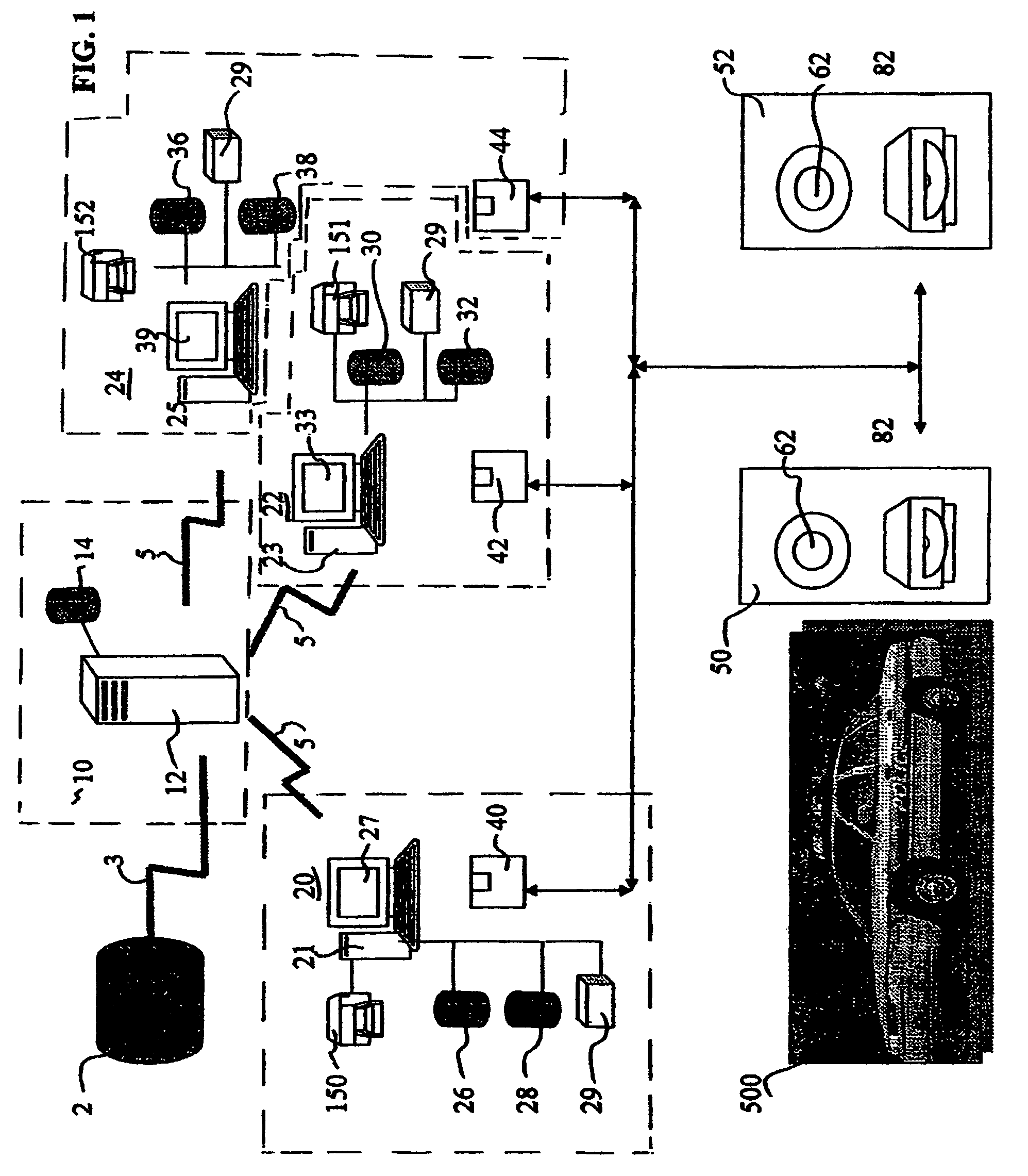
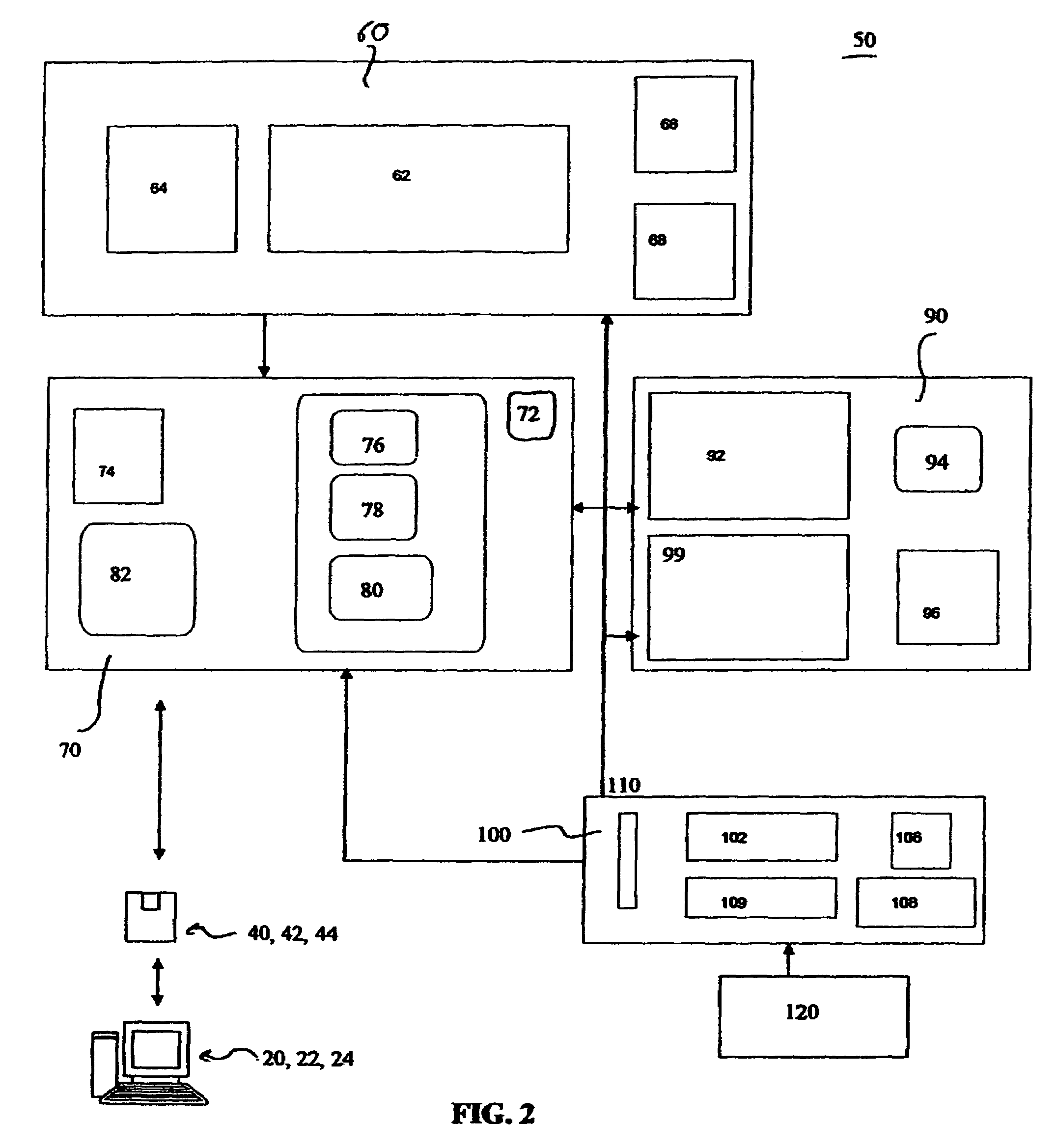
[0023]A preferred embodiment of the present invention is shown in FIGS. 1–3. FIG. 1 illustrates the system architecture of the present invention. FIGS. 1 and 2 illustrate the system and method used for both professional and non-professional thieves. FIGS. 1 and 3 illustrate the system and method used for locating professional thieves.

[0024]One aspect of the present invention is a system and method of conducting surveillance to detect stolen vehicles. The system is run and maintained at a service center 10. System subscribers, such as police departments and other law enforcement agencies, register with the service center 10. Subscribers register with the service center 10 via e-mail, phone, fax, or web site, or any such other method. Subscribers provide information about their jurisdiction, such as geographic location, known criminal activity, when shift changes occur.

[0025]The service center 10 has a central server 12. Storage, memory, and processing capabilities needed to operate t...


PUM


Abstract

The invention relates to a system and method of conducting surveillance of stolen vehicles. Stolen vehicle information is downloaded from a database to a central server. At the central server, vehicle information is parsed to the specific requirements. Each subscribing jurisdiction downloads its area-specific stolen vehicle database to a subscriber workstation, e.g., via the Internet or an intranet. Police cars have on-board mobile surveillance points having a camera and a processor. A copy of the area-specific stolen vehicle database is loaded into each car's processor. The mobile surveillance point reads license plates of vehicles in traffic, and the processor compares the license plates to stolen plate numbers stored in the database. The processor activates a signal to alert the officer. Stationary checkpoints located in the jurisdiction have a stationary surveillance point having a camera and a processor. The surveillance system stores images and creates a database of all vehicle plates in the area. The surveillance data is downloaded to the subscriber computer. The subscriber computer has a map database. A comparison algorithm identifies stolen vehicles in the area and their direction of travel, and displays the information on an area map. The analysis if performed with a spatial analysis algorithm along with temporal analysis using police officer's experience and knowledge of the area and vehicle types (make / model / value / etc) stolen. The police officer analyzes patterns of stolen vehicles and generates suggested new locations for checkpoints, narrowing in on a possible chop shop location.

Description

CROSS-REFERENCE TO RELATED APPLICATIONS[0001]“The present application is a continuation of U.S. patent application Ser. No. 10 / 409,083, filed on Apr. 9, 2003 by inventors Andrew J. Bucholz, Patrick D. Minix and Matthew D. Roberts and claims the benefit of the filing date of that application.”STATEMENT REGARDING FEDERALLY SPONSORED RESEARCH OR DEVELOPMENT[0002]The U.S. Government has a paid-up license in this invention and the right in limited circumstances to require the patent owner to license others on reasonable terms as provided for by the terms of Grant Number 2002-90606-VA-IJ awarded by the U.S. Department of Justice, Office of Justice Programs, National Institute of Justice.BACKGROUND OF THE INVENTION[0003]1. Field of the Invention[0004]The present invention relates broadly to systems and methods of surveillance, and particularly to surveillance of vehicles.[0005]2. Description of the Related Art[0006]According to Bureau of Justice Statistics, U.S. Department of Justice, auto...

Claims


Application Information

Patent Timeline
Patent Type & Authority Patents(United States)
IPC IPC(8): G08G1/017B60R25/10
CPCB60R25/305B60R25/10
Inventor BUCHOLZ, ANDREW J.MINIX, PATRICK D.ROBERTS, MATTHEW D.
Owner ENDEAVORING LLC
Why Eureka
Eureka Blog
Learn More