Device and method for controlling the optical power in a microscope

a technology of optical power and microscope, which is applied in the direction of photometry, instruments, electric discharge lamps, etc., can solve the problems of inflexible use in practice, propagation of measurement errors in calibration curves, and only detecting the actual crystal temperature with a delay in time, etc., to achieve convenient adjustment, high precision, and constant

Active Publication Date: 2006-05-16
LEICA MICROSYSTEMS CMS GMBH
View PDF10 Cites 2 Cited by
  • Summary
  • Abstract
  • Description
  • Claims
  • Application Information

AI Technical Summary

Benefits of technology

[0010]It is therefore an object of the present invention to provide a device and a method for controlling the optical power in a microscope, in particular, in confocal laser scanning microscope, whereby the optical power of the illuminating light beam of a microscope can be easily adjusted with high precision in a spectrally selective manner and, in particular, maintained constant.
[0012]In accordance with the present invention, it was discovered, first of all, that control of the optical power as a function of the temperature prevailing at the acousto-optical element is highly error-prone. In a next step, it was found that these errors can be avoided by a more direct procedure, i.e., by detecting the optical power itself instead of the temperature as an indirect parameter. The acousto-optical or electro-optical element can be operated by a control unit as a function of the measured optical power in such a manner that the optical power assumes a desired value. This allows the optical power to be controlled with high precision.
[0015]Particularly precise control of the optical power is possible when placing the measuring device directly upstream of the sample. By positioning the measuring device in this manner, it is possible to eliminate nearly all sources of error that occur along the illumination beam path and which can affect the optical power on the sample. The error sources to be mentioned in this connection are, in particular, the beam splitters or the deflection mirrors, which are generally provided with vapor-deposited, polarization-dependent coatings. Specifically, the optical power can thus be stabilized to below 1% change. It is also possible, in particular, to compensate for the non-linear properties of a piezoelectric transducer that is used to couple the RF wave into the acousto-optical crystal.
[0028]As described above in connection with the device according to the present invention, the optical power could be measured in an intermediate image in a particularly simple manner. In the intermediate image, the measurement could be carried out, for example, on a frame-by-frame basis, which is useful especially in the case of long-term measurements. However, it would also be conceivable to carry out the measurement each time before an image is recorded. For optical power measurement, it is advantageous to measure the optical power in a spectrally selective manner so as to be able to control the optical power at the acousto-optical and electro-optical elements based on the measured values in a spectrally selective manner as well.
[0029]Generally, it would be possible to correct minor fluctuations of the optical power by changing the RF amplitude of the high-frequency source that drives the acousto-optical element while maintaining the RF frequency constant. Given appropriate initial conditions, this should be easily possible within a temperature range of + / −1° C., in which the power change is less than 3%.
[0032]In the case of an AOBS used to spatially separate the illuminating light beam and the detection light beam, it has turned out to be advantageous to correct only the RF frequency because otherwise the excitation light component in the detection light beam is increased; it also being possible to, at least partially, compensate for this effect using a second downstream subcomponent of the AOBS.

Problems solved by technology

This method has the problem that, on the one hand, it only relies on the correctness of the underlying calibration curve and, on the other hand, that measuring errors in the calibration curves will propagate.
Moreover, its use in practice is extremely inflexible because a new calibration curve must first be generated for each illumination wavelength.
A further problem is that the actual crystal temperature can only be measured with a delay in time.
However, due to the absorption of the RF power in the crystal, the temperature can also change on a shorter time scale so that inaccuracies may creep in this manner as well.

Method used


Image

  • Device and method for controlling the optical power in a microscope
  • Device and method for controlling the optical power in a microscope

Examples


Embodiment Construction

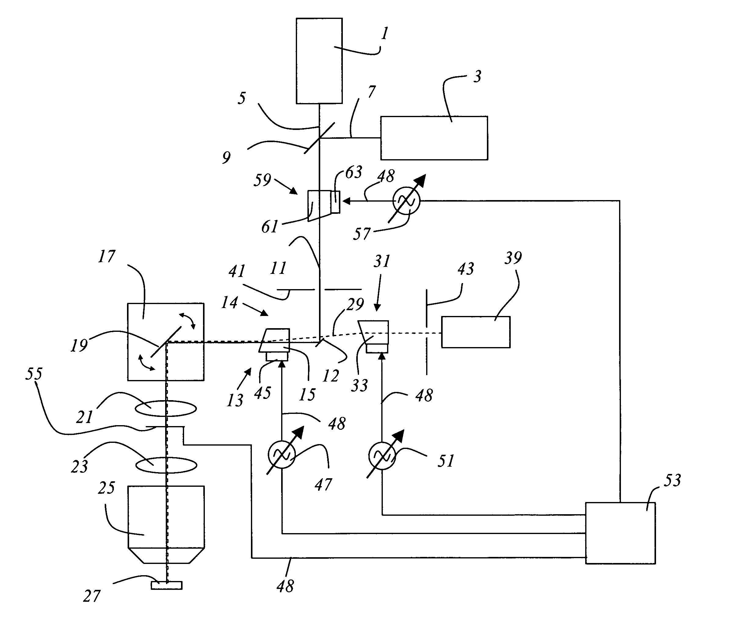
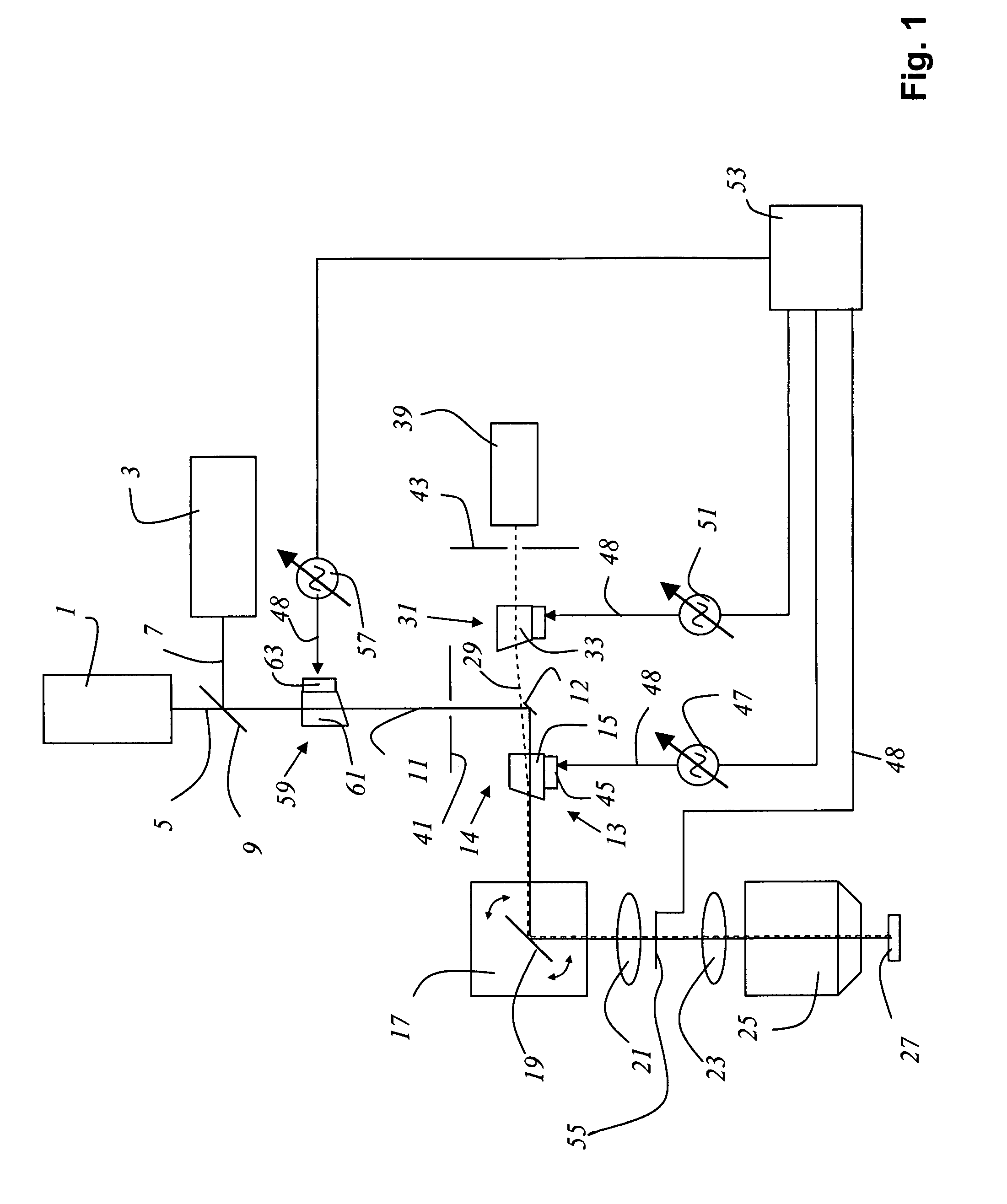
[0036]FIG. 1 shows a device according to the present invention for controlling the optical power in a microscope, the microscope shown in the Figure being designed as a confocal scanning microscope. The microscope includes two lasers 1, 3 whose emitted light beams 5, 7 have different wavelengths and which are combined into an illumination beam path 11 by dichroic beam combiner 9. In addition, the microscope has an acousto-optical element 59, which is designed as an AOTF 61.

[0037]After passage through the AOTF 61, illumination beam path 11 proceeds to a deflection mirror 12 and from there to a further acousto-optical element 13, which is designed as an AOTF 15. From acousto-optical element 13, illumination beam path 11 reaches a beam deflection device 17 which contains a gimbal-mounted scanning mirror 19 and guides the illumination beam path 11 through scanning optical system 21, tube optical system 23, and lens 25 and across or through sample 27.

[0038]A measuring device 55 is placed...


PUM


Abstract

An apparatus for controlling optical power in a microscope includes a measuring device for measuring the optical power, and a control unit for controlling a high-frequency source as a function of the measured optical power so as to achieve a selectable level of the optical power. The microscope includes a source providing light along an illumination beam path to a sample, a detector receiving detection light lead along a detection beam path from the sample, and an acousto-optical or electro-optical element located in the illumination beam path and driven by the high-frequency source.

Description

[0001]Priority is claimed to U.S. provisional application 60 / 544,207 filed on Feb. 12, 2004 and to German patent application DE 103 24 331.3, the subject matters of both of which are hereby incorporated by reference herein.[0002]The present invention relates to a device and a method for controlling the optical power in a microscope, in particular, in a confocal laser scanning microscope, including at least one light source, an illumination beam path leading the light to a sample, a detector, a detection beam path leading the detection light from the sample to the detector, and further including an acousto-optical or electro-optical element in the illumination beam path.BACKGROUND[0003]Devices and methods for controlling the optical power in a microscope are known in the field. In the devices of the type described, fast acousto-optical or electro-optical elements are generally used to adjust the optical power of an illuminating light beam in a nearly infinitely variable and spectrall...

Claims


Application Information

Patent Timeline
IPC IPC(8): H01J3/14H01J40/14H01J5/16G01J1/42G02B21/00
CPCG02B21/0024G01J1/4257
Inventor MOELLMANN, KYRABIRK, HOLGER
Owner LEICA MICROSYSTEMS CMS GMBH
Why Eureka
Try Eureka