
Transducer structure that operates with acoustic waves

a transducer and wave technology, applied in piezoelectric/electrostrictive/magnetostrictive devices, impedence networks, piezoelectric/electrostriction/magnetostriction machines, etc., can solve the problems of non-optimal filters with unsatisfactory characteristics, most not optimized simultaneously, etc., to achieve the effect of improving characteristics

Inactive Publication Date: 2006-05-09
SNAPTRACK
View PDF9 Cites 23 Cited by
  • Summary
  • Abstract
  • Description
  • Claims
  • Application Information

AI Technical Summary

Benefits of technology

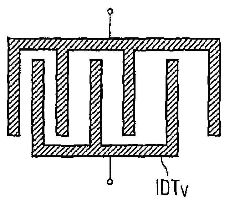
[0005]It is the object of the present invention to provide a transducer structure operating with acoustic waves which comprises at least one further degree of freedom in the optimization, and with which, for example, a reactance filter with improved characteristics can be constructed.
[0008]It has been shown that a better electric conformance can be achieved in a resonator-filter environment with such a variation of the finger period. The filter can be a DMS filter, a TCF filter, or a reactance filter. In particular, the reflection at the input or, respectively, output of the filter can be minimized with a transducer structure with varying finger period. With the invention, for example, the voltage standing wave ratio (VSWR) can be reduced in a reactance filter used in the high-frequency range. Finally, with resonators according to the invention, reactance filters can be constructed that exhibit an improved passband and, in particular, an improved insertion loss.
[0016]With an embodiment of the invention, a spreading of the resonance can be achieved for the individual resonator, whereby simultaneously the shape of the anti-resonance remains unchanged. In this manner, a reactance filter can be achieved which exhibits an increased bandwidth without the other characteristics of the filter simultaneously deteriorating. With an embodiment of the invention, reactance filters may be achieved via suitable selected variations of the finger separations and finger widths that, given the same bandwidth, overall show an improved electrical conformance in the transmission range of the filter.
[0018]Particularly advantageous are inventive resonators or, respectively, filters produced from them, constructed with poorer electro-acoustic coupling, for example, on lithium tantalate with low layer thickness. Under such conditions, a better electrical conformance is achieved via an improved electro-acoustic behavior.

Problems solved by technology

However, its disadvantage is that these characteristics can mostly not be simultaneously optimized, such that only one suitable combination of characteristics can always be achieved, but not one filter optimal in all characteristics.
Particularly in broadband filters that exhibit a relative bandwidth of more than 2%, or in filters that are constructed on substrates with lower electro-acoustic coupling (for example, on LiTaO3 in connection with smaller layer thickness or on quartz), an optimization attempt can only result in non-optimal filters with unsatisfactory characteristics.

Method used


Image

  • Transducer structure that operates with acoustic waves
  • Transducer structure that operates with acoustic waves
  • Transducer structure that operates with acoustic waves

Examples


Embodiment Construction

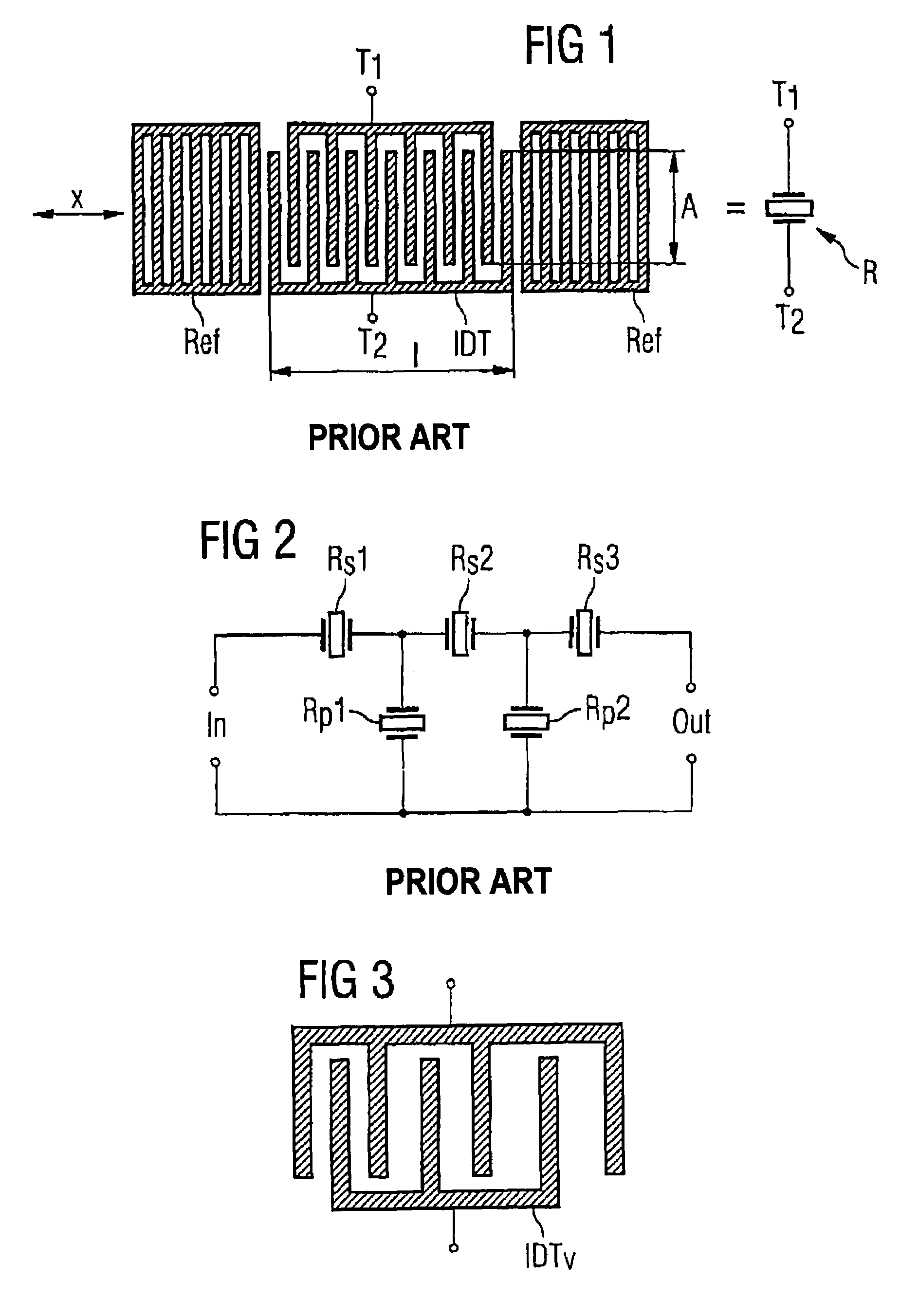
[0027]A resonator operating with acoustic waves in shown in FIG. 1. The metallic electrode structures (for example, comprising aluminum, an aluminum alloy, or a multi-layer structure comprising an aluminum layer) are applied to a piezoelectric substrate. The resonator consists of an inter-digital transducer IDT that is arranged between two reflectors Ref. Each inter-digital transducer IDT comprises of two telescoped comb-like electrodes that are connected with connections T1 and T2. The electrode fingers of the inter-digital transducer of known resonators exhibit a uniform electrode finger separation P that typically is defined as the distance between the finger centers of two adjacent electrode fingers. The circuit symbol for such a resonator R is shown in the right half of the image. Known possibilities to adjust the electrical properties of such a resonator R exist in the variation of the aperture A, the number N of the electrode fingers, the finger separation P of the electrode ...


PUM


Abstract

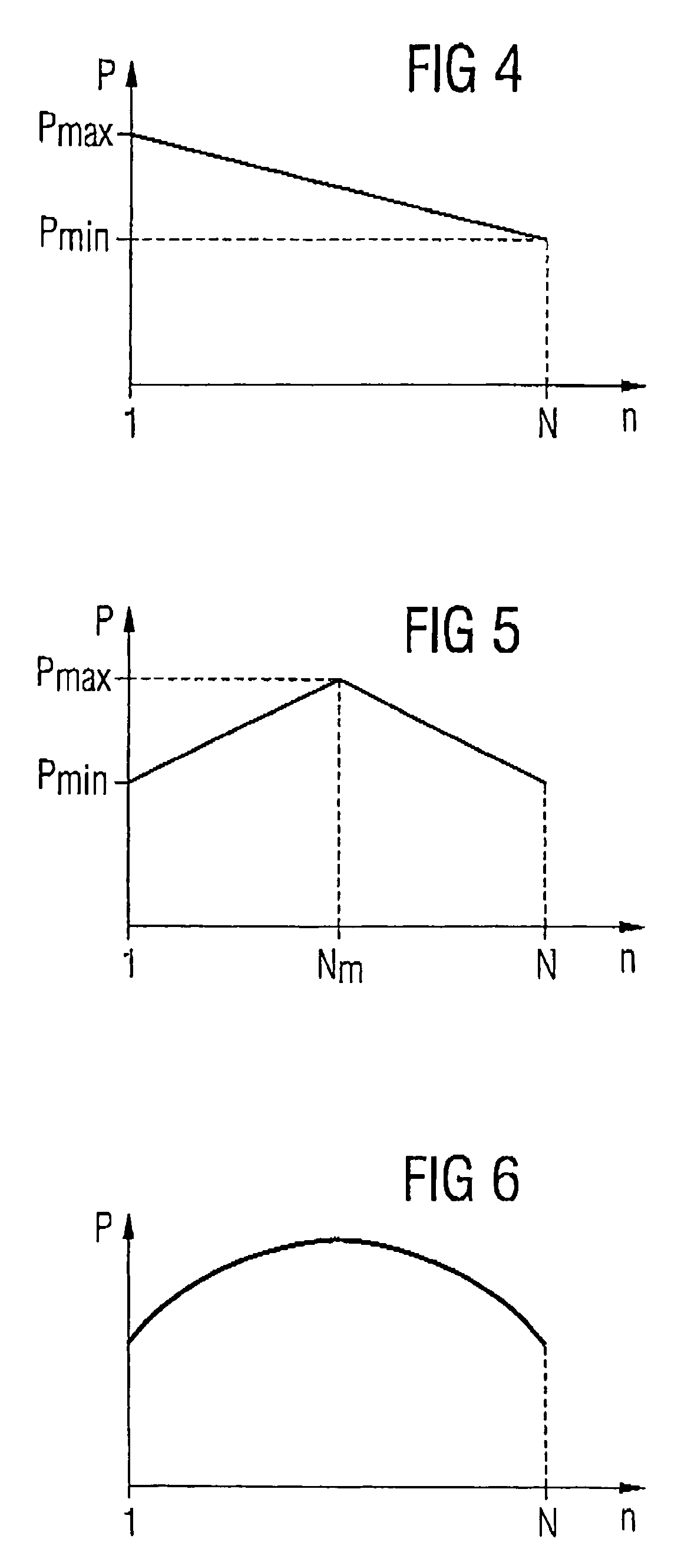
For improved conformance of a filter operating with acoustic waves, a transducer structure is provided in which the separations between respectively two adjacent electrode fingers of an inter-digital transducer (IDTv) vary over the length of the transducer. The variation thereby preferably follows a continuous distribution function. Reactance filters that are provided with such filters in the serial branch show an improved electrical conformance in the transmission range.

Description

BACKGROUND OF THE INVENTION[0001]The invention concerns a transducer structure operating with acoustic waves, particularly for a surface wave filter (called an OFW or also a SAW filter) or an S-BAR filter (bulk acoustic wave resonator).[0002]In filters operating with acoustic waves (particularly in SAW filters) in particular transducer structures operating with acoustic waves (for example, SAW resonators) are used as impedance elements. Such a resonator is constructed on the surface of a piezoelectric substrate from metallic electrode structures, and comprises an inter-digital transducer with at least two connections that is normally arranged between two reflectors. Known resonators comprise inter-digital transducers that are characterized by a uniform finger period and finger width over the entire transducer. Each resonator thereby exhibits what is known as a resonance frequency and an anti-resonance frequency. The frequency position and the intensity of resonance and anti-resonanc...

Claims


Application Information

Patent Timeline
Patent Type & Authority Patents(United States)
IPC IPC(8): H01L41/08H03H9/145H03H9/25H01L41/09H03H9/64
CPCH03H9/14555
Inventor BAUER, THOMASBUNNER, MARTINDETLEFSEN, ANDREASRITTER, DIETMAR
Owner SNAPTRACK
Learn More