
Positron annihilation monitor and method for detecting hazardous materials

a technology of annihilation monitor and detector, which is applied in the direction of material analysis through secondary emission, instruments, and withdrawing sample devices, etc., can solve the problems of inability to detect hazardous materials, and inability to detect biological hazards

Inactive Publication Date: 2006-05-09
ALERTTECHSYST
View PDF20 Cites 14 Cited by
  • Summary
  • Abstract
  • Description
  • Claims
  • Application Information

AI Technical Summary

Benefits of technology

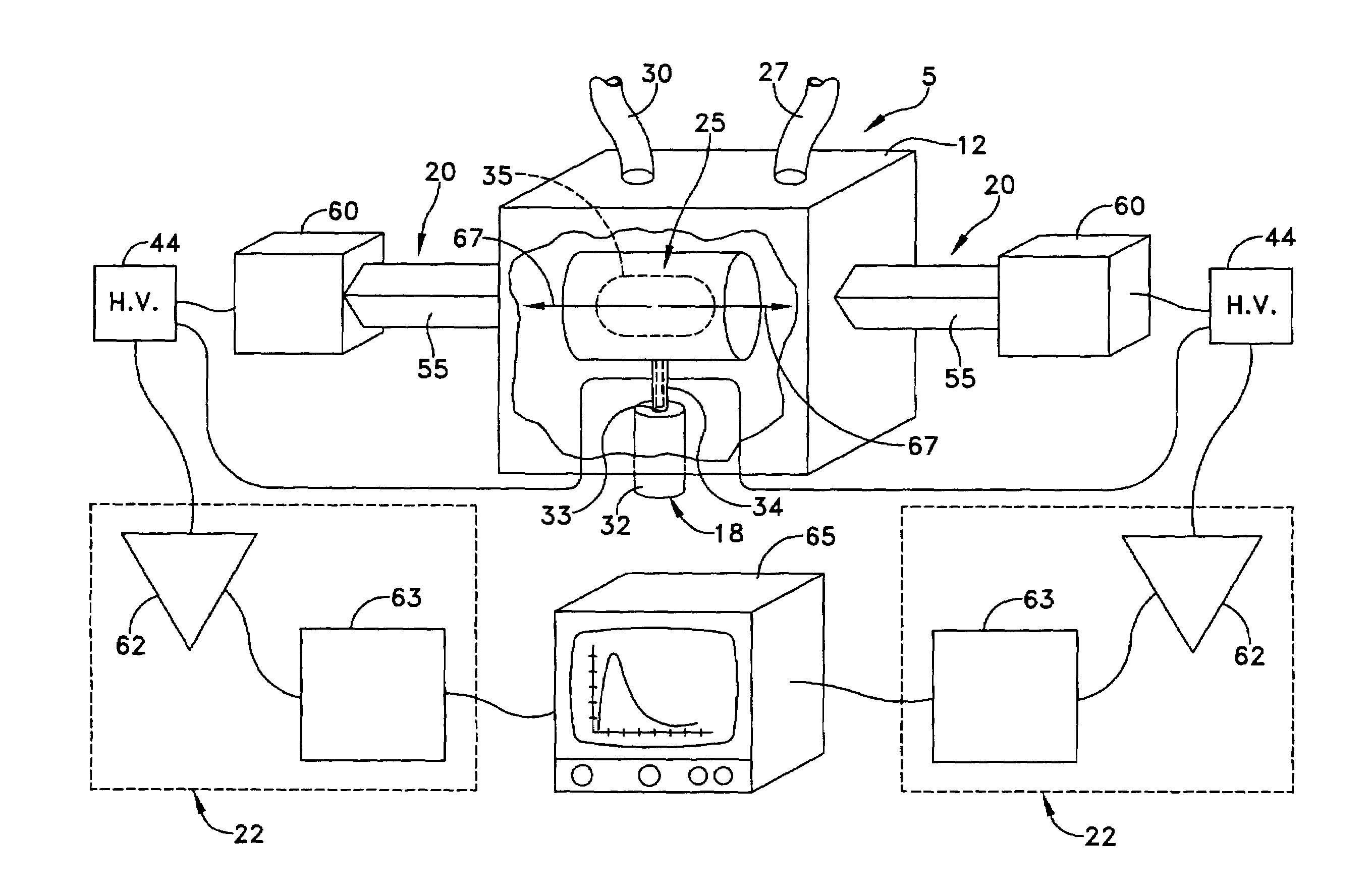
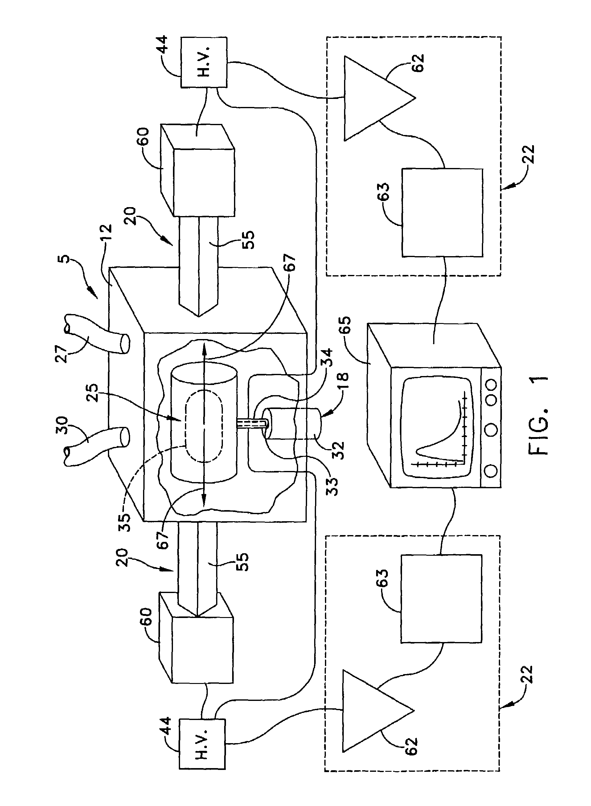
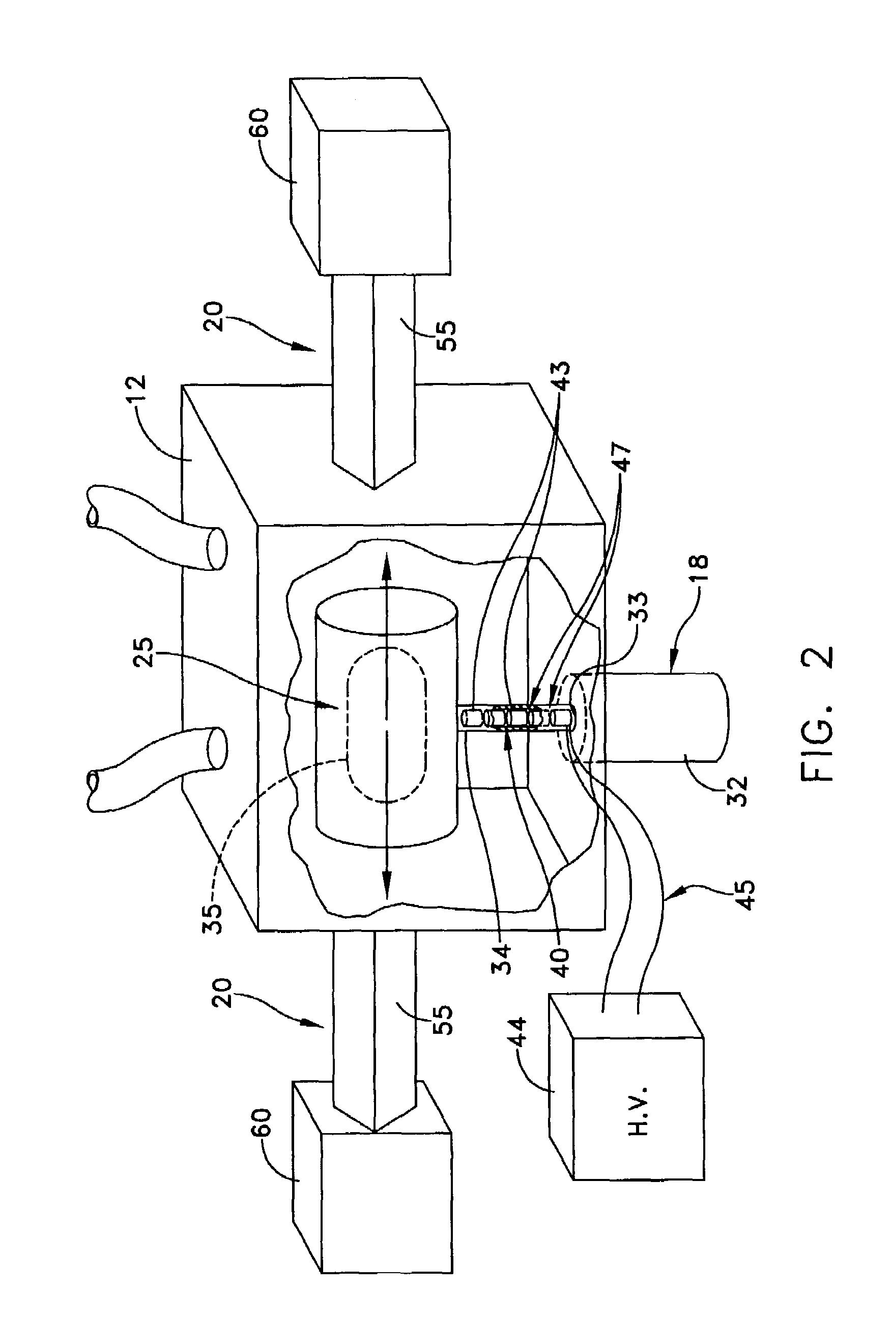
[0012]The present invention provides a device for measuring the presence of a small concentration of at least one hazardous material within a vessel. A positron source emits positrons into an annihilation region of the vessel that is spaced apart from the positron source. A plurality of species of positronium are formed from the positrons as they interact with a sample of the ambient environment, e.g., an ambient air sample, disposed within the vessel. The annihilation region within the vessel is positioned such that at least a portion of the sample to be monitored must pass in annihilation proximity of the positrons so as to form at least one of the species of positronium. Two gamma ray detectors are located externally of the vessel, and shielded from the positron source, for detecting gamma rays generated primarily by the absorption of the species of positronium within the annihilation region.

Problems solved by technology

Significantly, such prior art sensors are essentially blind to biological hazards.
There are many substances which have very small vapor pressures, but whose presence in air is nonetheless undesirable because they are very toxic or indicate the presence of unwanted substances hazardous chemicals, biological agents, explosives, drugs, etc.
Current detection methods for BCA hazards are extremely slow, and are often based upon complicated chemical or mechanical concepts, use of multi-step and labor intensive approaches, or the need for replaceable supplies (consumables).
In addition, such prior art devices are often very large (not portable) and expensive.
However, in the real world, they are unlikely to be presented to a detector with a sufficient volume of saturated air to make such detection easy.

Method used


Image

  • Positron annihilation monitor and method for detecting hazardous materials
  • Positron annihilation monitor and method for detecting hazardous materials
  • Positron annihilation monitor and method for detecting hazardous materials

Examples


Embodiment Construction

[0026]This description of preferred embodiments is intended to be read in connection with the accompanying drawings, which are to be considered part of the entire written description of this invention. The drawing figures are not necessarily to scale and certain features and atomic structures formed by the method of the invention may be shown highly exaggerated in scale or in somewhat schematic form in the interest of clarity and conciseness. In the description, relative terms such as “horizontal,”“vertical,”“up,”“down,”“top” and “bottom” as well as derivatives thereof (e.g., “horizontally,”“downwardly,”“upwardly,” etc.) should be construed to refer to the orientation as then described or as shown in the drawing figure under discussion. These relative terms are for convenience of description and normally are not intended to require a particular orientation. Terms including “inwardly” versus “outwardly,”“longitudinal” versus “lateral” and the like are to be interpreted relative to on...


PUM

PropertyMeasurementUnit
sum energyaaaaaaaaaa
atomic numberaaaaaaaaaa
speedaaaaaaaaaa

Abstract

A monitor is provided for measuring the presence of a small concentration of at least one hazardous material within a vessel. A positron source emits positrons into an annihilation region of the vessel. A plurality of species of positronium are formed from the positrons as they interact with a sample of the ambient environment disposed within the vessel. At least one gamma ray detector is located externally of the vessel for detecting gamma rays generated primarily by the absorption of the species of positronium within the annihilation region. A method is also provided where a source of positrons is arranged to direct positrons into a vessel containing a specimen of gas and a contaminant to form species of positronium. The timing of the application of positrons is sensed along with the annihilation of each of the plurality of species of positronium. The time delay between the time of application of each positron and the annihilation of the of positronium is measured to obtain a decay rate characteristic of the specimen of gas.

Description

CROSS REFERENCE TO RELATED APPLICATIONS[0001]This application claims priority from now abandoned Provisional Patent Application Ser. No. 60 / 354,840, filed Feb. 6, 2002, and entitled POSITRON AIR MONITOR (PAM).FIELD OF THE INVENTION[0002]The present invention generally relates to hazardous material sensors, and more particularly to sensors for use in monitoring the level of hazardous contaminants in the ambient environment.BACKGROUND OF THE INVENTION[0003]Approximately five and three quarter million shipping containers a year, or ninety-five percent of all international origin goods, arrive in the U.S. by sea. At U.S. ports, inspecting a 20 to 40 foot long shipping container can take four customs inspectors about four hours. At that rate, often fewer than two percent are opened for inspection, and the great majority never pass through any existing sensors, e.g., x-ray machines, gamma-ray probes, or the like. In addition, U.S. borders to the north and south accommodate 125 million veh...

Claims


Application Information

Patent Timeline
Patent Type & Authority Patents(United States)
IPC IPC(8): G01N33/00G01N1/02G01N23/22
CPCG01N23/22Y10T436/163333G01N2001/022
Inventor SMITH, GERALD
Owner ALERTTECHSYST
Learn More