
Method and device for adjusting variable compression in a combustion engine

a technology of variable compression and combustion engine, which is applied in the direction of engine controllers, machines/engines, electric control, etc., can solve problems such as reducing efficiency

Inactive Publication Date: 2006-05-02
ROBERT BOSCH GMBH
View PDF6 Cites 6 Cited by
  • Summary
  • Abstract
  • Description
  • Claims
  • Application Information

AI Technical Summary

Benefits of technology

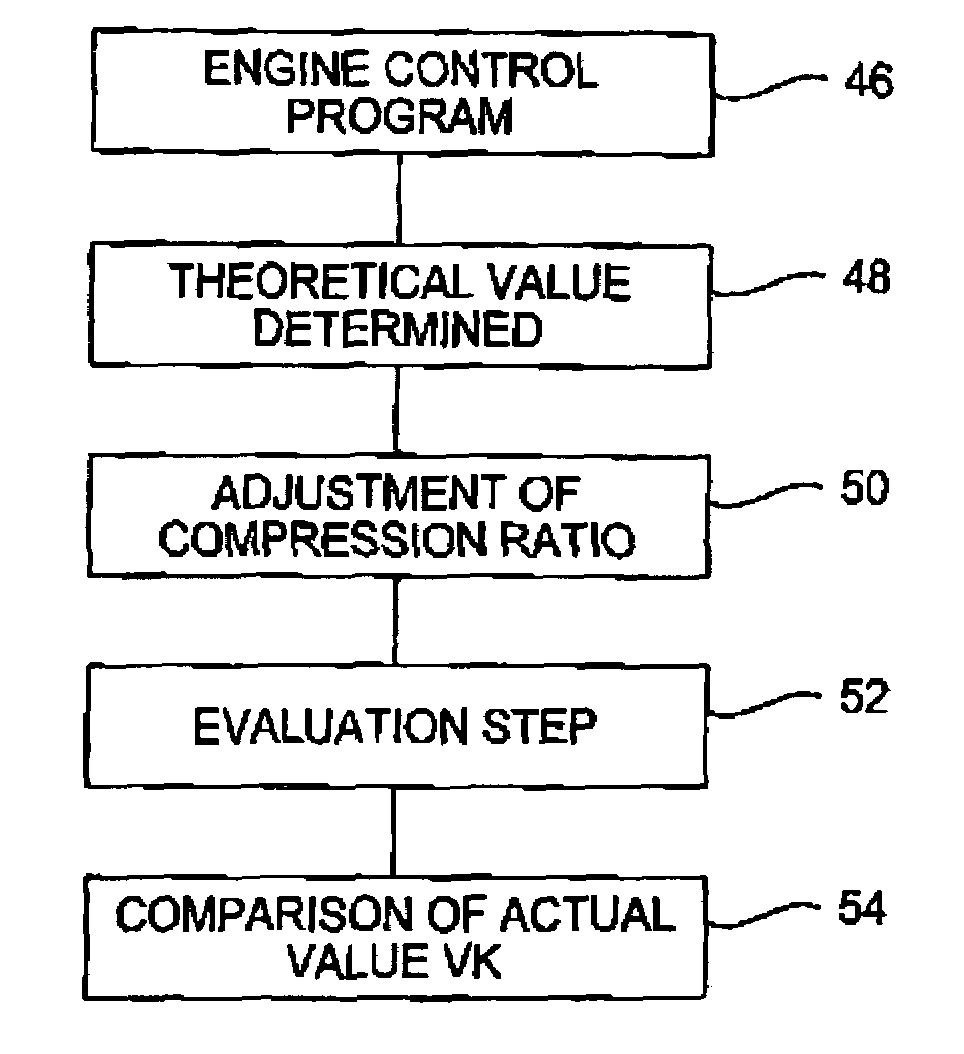
[0013]With the above features, the object of the present invention is resolved completely. The determination of the actual value of the compression permits regulation of the compression in a closed control loop. The disadvantages of the known controlling of the actuator of the compression on the basis of an open timing chain thereby are minimized. With the complexity of the total system of a combustion engine with the plurality of parameters responsible for the occurrence of knocks (compression ratio, fuel quality, intake temperature, ignition time point, . . . ), the confirmation permits a better association of knocking combustions to the causally responsible parameters, and therewith, a targeted countermeasure.
[0015]The present invention, in contrast, permits a correction of the compression when the compression is responsible causally for the occurrence of knocks. In conclusion, a combustion engine with variable compression can be driven with improved efficiency, which is advantageous for performance as well as for exhaust quality.
[0017]The use of a combustion chamber pressure sensor permits a direct determination of the compression ratio on the basis of a thermodynamic correlation. In this manner, the compression can be determined accurately and reproducibly.
[0021]This embodiment makes possible the elimination of the unknown parameters already from a pressure progression reduced to two measured values.

Problems solved by technology

The non-optimal efficiency caused by the premature ignition is then further impaired under certain circumstances by a reduction of the compression, which reduces the efficiency.

Method used


Image

  • Method and device for adjusting variable compression in a combustion engine
  • Method and device for adjusting variable compression in a combustion engine
  • Method and device for adjusting variable compression in a combustion engine

Examples


Embodiment Construction

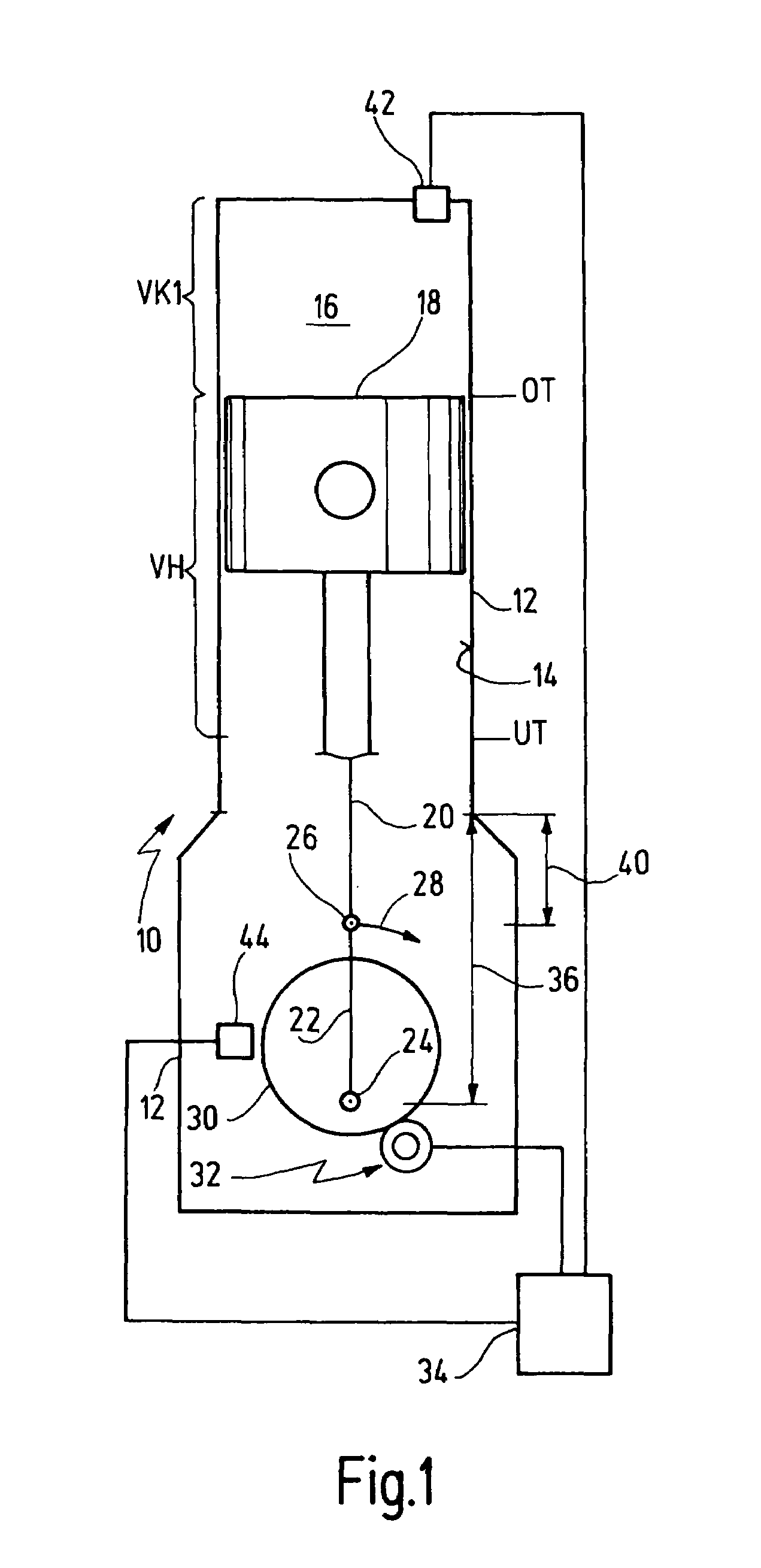
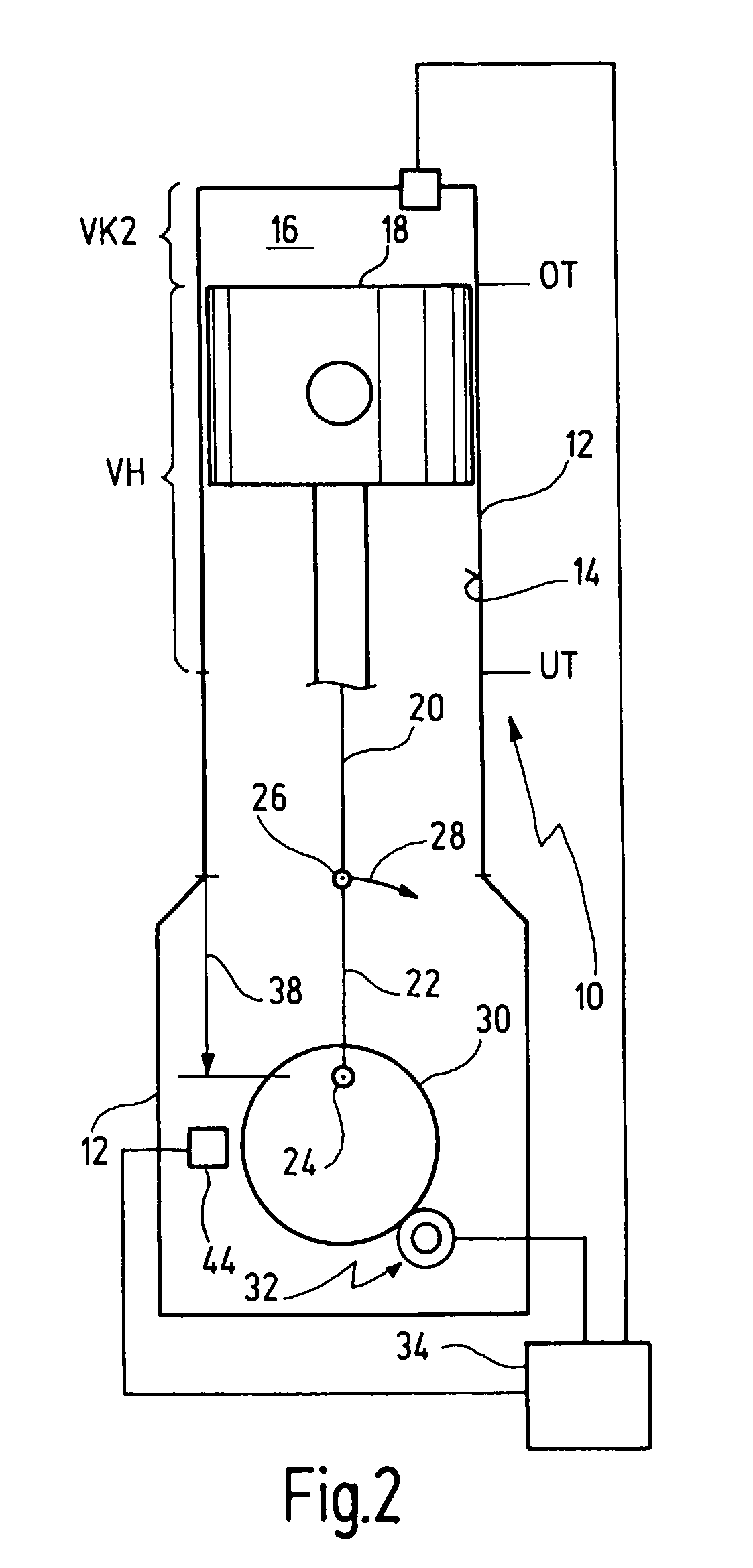
[0035]In FIG. 1, a combustion engine 10 is shown in markedly simplified form. The combustion engine 10 has an engine block, in which the cylinders 14 are arranged. FIG. 1 shows a cylinder 14 of a multiple-cylinder combustion engine. The remaining cylinders, for example, are arranged behind the shown cylinder 14, so that FIG. 1 corresponds to a schematized front view of a multi-cylinder in-line engine. In the cylinder 14, a combustion chamber 16 is movably sealed up by a piston 18, whereby the piston 18 is guided into the cylinder. The piston 18 is connected via a piston rod 20 to a piston rod bearing 26 of a crankshaft 22, which is rotatably supported in main bearings 24. The arrow 28 indicates the rotational direction of the crankshaft 22. For realization of a variable compression, the main bearings 24 of the crankshaft 22 are not supported directly in the engine block 12, rather in eccentric rings 30.

[0036]The eccentric rings 30 are rotatably supported in the engine block 12. The ...


PUM


Abstract

A method for operating a combustion engine (10) with a variable compression ratio includes the following steps: determining a theoretical value for the compression ratio; adjusting the compression ratio to the theoretical value; and correcting the adjusted compression ratio as a function of signals of a sensor mechanism of the combustion engine (10). The step of correcting includes the step of determining an actual value of the compression ratio. In addition, a device for performing the method is proposed.

Description

BACKGROUND OF THE INVENTION[0001]The present invention relates to a method for operating an internal combustion engine with a variable compression ratio with the following steps: determining a theoretical value for the compression ratio; adjusting the compression ratio to the theoretical value; and correcting the adjusted compression ratio as a function of signals of a sensor mechanism of the combustion engine.[0002]In addition, the present invention relates to a device for operating an internal combustion engine, which has at least one controller for adjusting a variable compression ratio to a theoretical value and a sensor mechanism, which is sensitive to changes of the compression ratio.[0003]Such a method and device are known from DE 199 50 682 A1.[0004]Methods for operating a multi-cylinder combustion engine with a variable compression ratio, as well as a control apparatus for controlling the method, are known, respectively, from DE 100 51 271.[0005]These documents show a combu...

Claims


Application Information

Patent Timeline
Patent Type & Authority Patents(United States)
IPC IPC(8): F02D15/02F02B75/04F02D15/00F02D45/00F02D35/02
CPCF02B75/04F02D35/023F02D15/00
Inventor KASSNER, UWE
Owner ROBERT BOSCH GMBH
Learn More