System for reducing noise in the reproduction of recorded sound signals

a sound signal and reproduction technology, applied in the field of electrical signal processing, can solve the problems of ineffective suppression of noise components of opposite polarities, difficulty in distinguishing drum transients from noise transients, blankers sometimes producing audible artifacts, etc., to achieve effective treble attenuation characteristic, reduce minimum cutoff frequency, and reduce noise

Inactive Publication Date: 2006-04-25
PACKBURN ELECTRONICS
View PDF5 Cites 10 Cited by
  • Summary
  • Abstract
  • Description
  • Claims
  • Application Information

AI Technical Summary

Benefits of technology

[0007]The third system, a “Continuous Noise Suppressor”, reduces noise of a continuous nature, usually referred to as “hiss” or, roughly, as “white noise”, by means of an electronic circuit wherein the upper limit of the band width of the signal is automatically and continually adjusted in accordance with the relationship of (1) the peak amplitude of the rate of change of the signal with respect to time (i.e. the second derivative of the signal) to (2) the instantaneous amplitude of the signal within a selected frequency band. The Continuous Noise Suppressor disclosed herein has a more effective treble attenuation characteristic with a lower minimum cutoff frequency and a more rapid response to the changing dynamics of a recording, thus further reducing to the acute listener audibility of the continual modications of the cutoff frequency.

Problems solved by technology

This system was not effective in suppressing noise components of opposite polarity and non-matching amplitude.
However, in some cases, in program material with very steep transients, such as commonly found in recordings of guitar, harpsichord, pizzicato strings and an occasional strongly attacked vocal note, the Blanker sometimes produced audible artifacts.
It also had some trouble in distinguishing drum transients from noise transients, and in suppressing low level noise transients in low signal level areas.

Method used


Image

  • System for reducing noise in the reproduction of recorded sound signals
  • System for reducing noise in the reproduction of recorded sound signals
  • System for reducing noise in the reproduction of recorded sound signals

Examples


Embodiment Construction

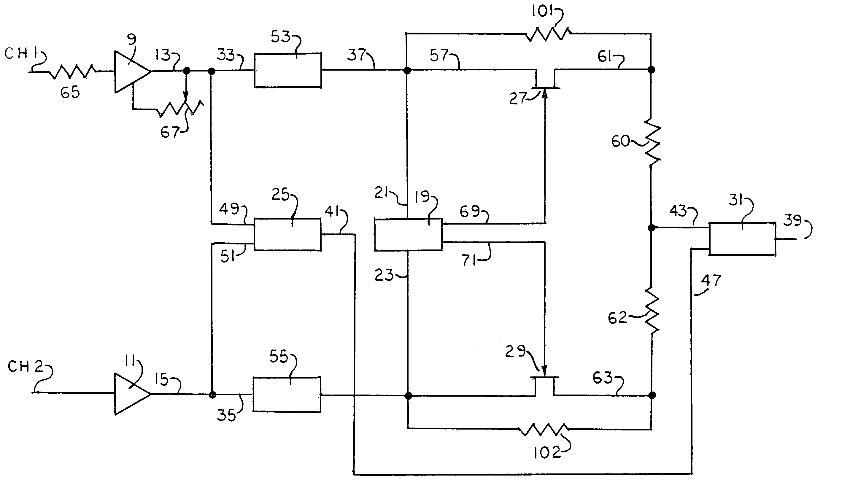
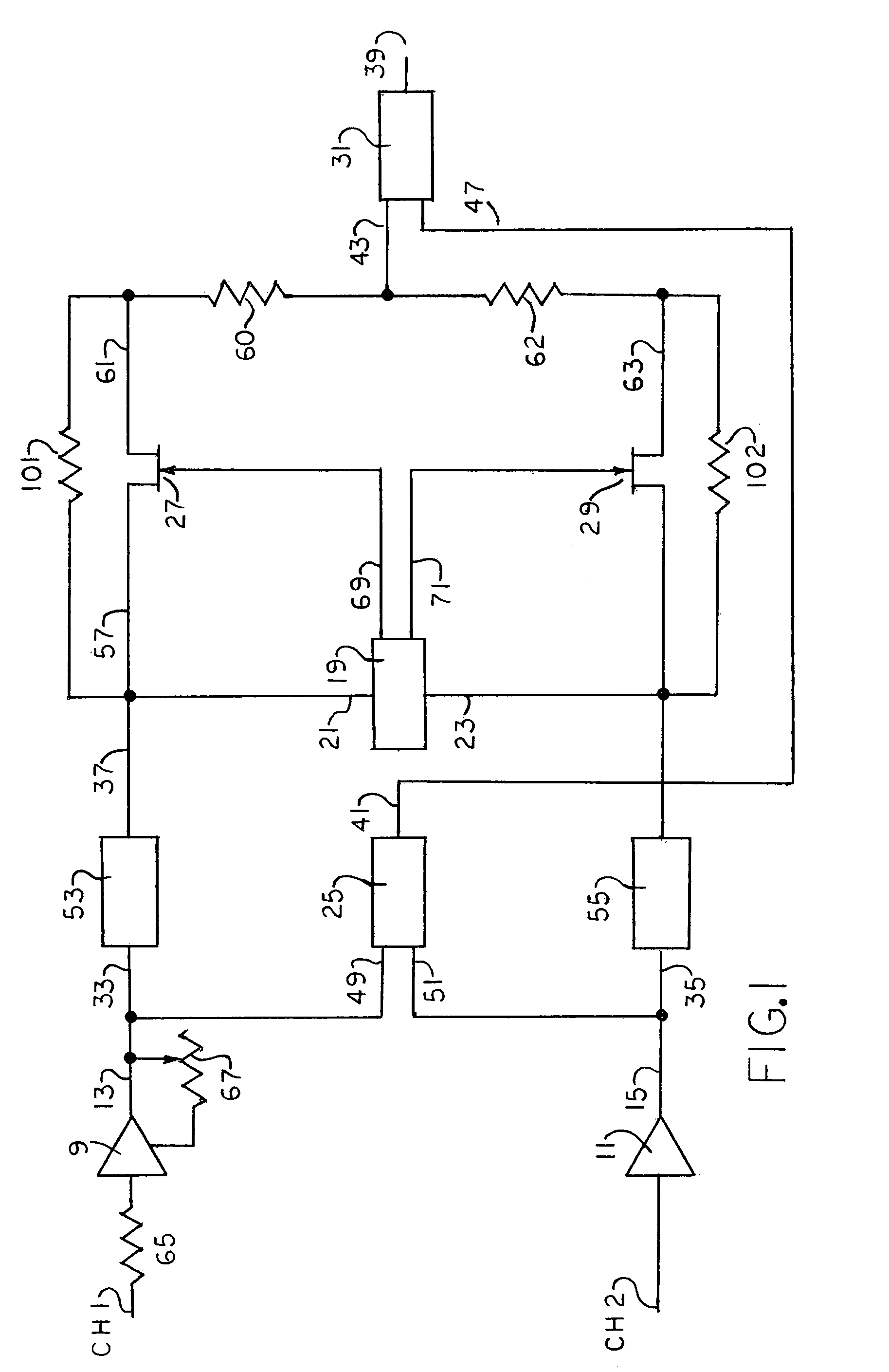
[0012]The three systems or processing stages for removing noises from sound signals emanating from such sources as sound recordings, radio broadcasts and the like, may be employed individually or in combination, as dictated by the requirements of the job at hand. The first disclosed system, the Switcher, two signals which are substantially identical in program content, but which may differ in total signal amplitude due to differing noise content, are received simultaneously on respective channels and appropriate electronic circuitry compares to two input (total) signals and transmits to the recording or reproducing apparatus either: 1. an equal mixture (average) of the two input signals, or 2 the input signal on one of the channels. When that input signal has an amplitude which is lower than the average of the amplitudes of the two input signals by more than a predetermined threshhold amount.

The Switcher

[0013]Referring now to FIG. 1, there is illustrated a system which includes two ...


PUM


Abstract

A noise reduction system is connected to at least two input channels for receiving input signals that have substantially identical program content but differing instantaneous noise transients. The system selects a filtered input signal that has the lowest instantaneous noise transient level. In another aspect, the noise reduction system removes instantaneous transient noise from an input signal by way of a blanker. The blanker includes a switch that opens whenever a band-pass filtered input signal is greater than the average level of the signal by a predetermined proportional amount. The input signal also includes continuous noise that is removed by a continuous noise suppressor. The continuous noise is removed by a low pass filter whose corner frequency is responsive to a differentiated input signal divided by the program component signal, or vice versa. In another aspect, the noise reduction system includes at least two of a switcher, blanker or continuous noise suppressor in connected in series to remove both instantaneous noise transients and continuous noise from an input signal.

Description

BACKGROUND OF THE INVENTION[0001]The present invention relates to the processing of electrical signals in connection with the recording and reproduction of sound, and in particular to the reproduction and the rerecording and playback of previously recorded sound signals.[0002]The applicant is co-patentee of U.S. Pat. Nos. 4,155,041; 4,151,471 and 4,259,742 and is sole patentee of U.S. Pat. No. 4,322,641. These patents, which are incorporated herein by reference, are all concerned with the reduction of extraneous noises in the reproduction of analog sound recordings. These patents disclose three distinctly different and complementary systems for eliminating or reducing noises in the playback of old cylinder and disc records. The first of these systems eliminates noises in the reproduction of monophonic disc or cylinder records by virtue of a switching process that selects reproduction from the momentarily quieter groove wall or from an equal mixture of the two, requiring that the rec...

Claims


Application Information

Patent Timeline
IPC IPC(8): H04B15/00
CPCH04H60/04H03G5/22
Inventor PACKARD, THOMAS N.
Owner PACKBURN ELECTRONICS
Why Eureka
Try Eureka