
Optical information recording medium and method of recording and reproducing information on and from optical information recording medium

a technology of optical information and recording medium, which is applied in the direction of optical recording/reproducing/erasing methods, instruments, photomechanical equipment, etc., can solve the problems of difficult to design an organic dye for recording/reproducing light with a short wavelength, difficult to achieve a high transfer rate, and likely insufficient recording sensitivity. achieve the effect of high transfer ra

Inactive Publication Date: 2006-04-25
HITACHT MAXELL LTD
View PDF8 Cites 5 Cited by
  • Summary
  • Abstract
  • Description
  • Claims
  • Application Information

AI Technical Summary

Benefits of technology

[0017]Furthermore, in the optical information recording medium to which the present invention is applied, the recording layer is characterized by that information is recorded and reproduced when the recording layer is irradiated from the side or the opposite side of the substrate with a laser beam.

Problems solved by technology

To increase the speed demanded for the optical information recording medium, a conventional write-once medium has the following problem: for example, in the case where an organic dye is used as the recording material, recording sensitivity is likely to be insufficient when high-speed recording is performed by increasing a linear velocity of the medium.
Thus, it is difficult to achieve a high transfer rate.
In addition, the conventional write-once medium has another problem that it is hard to design an organic dye for recording / reproducing light with a short wavelength.
However, this phase-change process requires a long time to complete the crystallization, and therefore it is difficult to achieve a high transfer rate.
However, it is difficult to utilize this phase-change (crystalline to amorphous) recording material for the write-once medium because of the following reason.
Thus, even when information is recorded and reproduced by use of a blue laser with a wavelength of 405 nm, the recording material cannot be utilized for the write-once medium.

Method used


Image

  • Optical information recording medium and method of recording and reproducing information on and from optical information recording medium
  • Optical information recording medium and method of recording and reproducing information on and from optical information recording medium
  • Optical information recording medium and method of recording and reproducing information on and from optical information recording medium

Examples


first embodiment

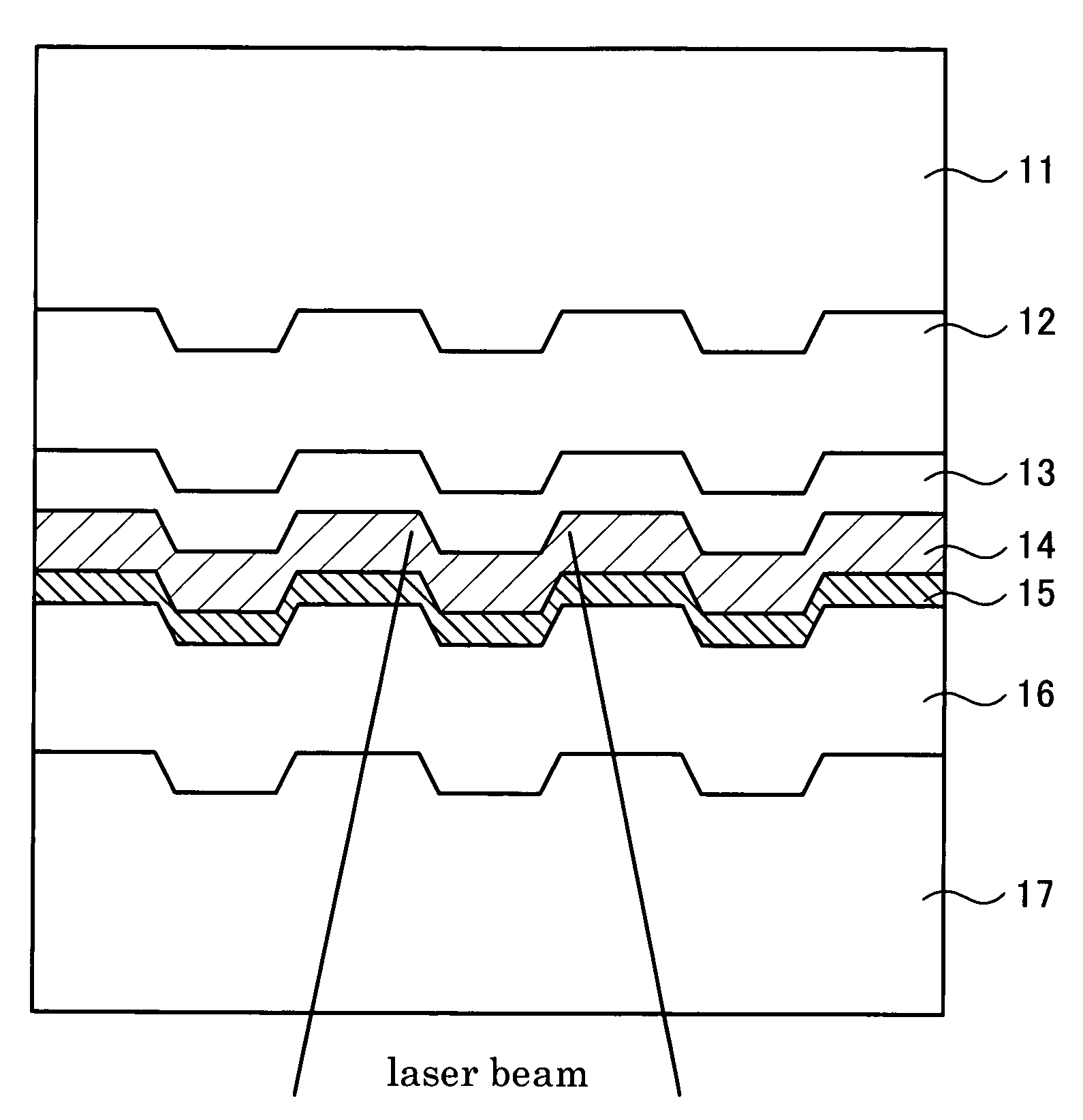
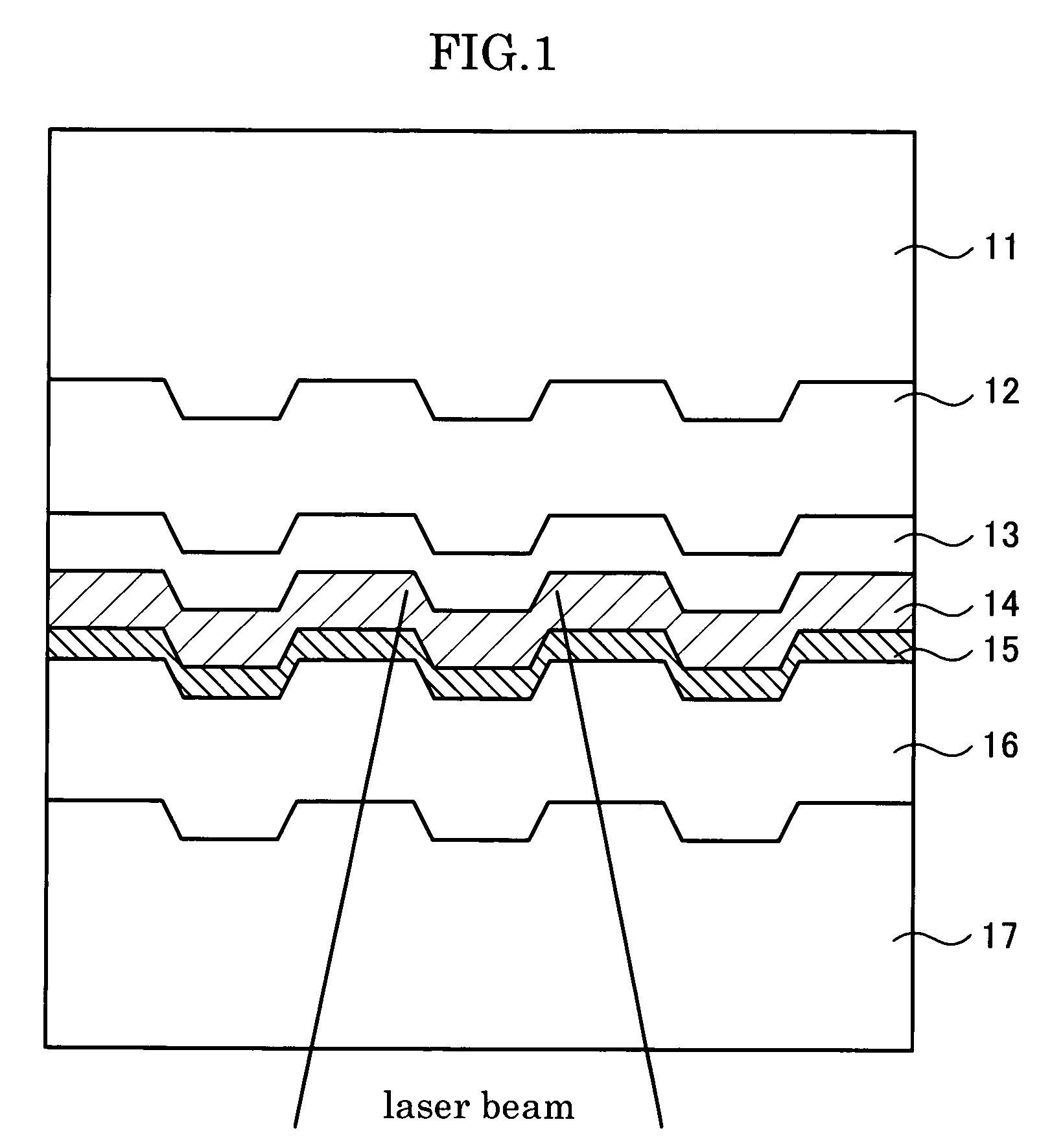
[0029]FIG. 1 is a view for explaining the structure of an optical information recording medium in the first embodiment to which the present invention is applied. A single-panel optical disk of a film incident light type shown herein is laminated by in the order of a transparent substrate 11, a reflective layer 12, a first dielectric layer 13, a recording layer 14, a write-protect layer 15 and a second dielectric layer 16. Further, UV curing resin forms a transparent cover layer 17 on the second dielectric layer 16. The recording layer 14 is made of a phase-change material, and the write-protect layer 15 is provided to abut on the side of the recording layer 14, where a laser beam enters from. The laser beam passes through the cover layer 17, the second dielectric layer 16 and the write-protect layer 15 to enter the recording layer 14, thereby recording and reproducing information. Herein, a laser beam with a wavelength of 500 nm or less is used for recording and reproducing informat...

second embodiment

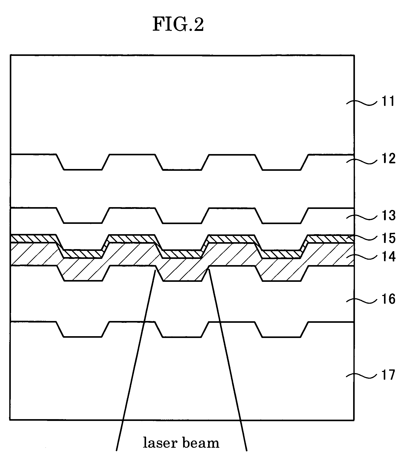
[0048]FIG. 2 is a view for explaining the structure of the optical information recording medium in a second embodiment. In a single-panel optical disk of a film incident light type shown herein, a write-protect layer 15 is provided to abut on a side of a recording layer 14, which is opposite the side which a laser beam enters from. As shown in FIG. 2, sequentially stacked on a substrate 11 are a 50 nm-thick Ag98Ru1Au1 reflective layer 12, a 18 nm-thick (ZnS)80(SiO2)20 (mol %) first dielectric layer 13, a 3 nm-thick Co3O4 (atom %) write-protect layer 15, a 15 nm-thick Ge33Sb13Te54 (atom %) recording layer 14, a 60 nm-thick (ZnS)80(SiO2)20 (mol %) second dielectric layer 16 and a cover layer 17. Each layer is formed in the same way as the first embodiment.

[0049]By providing the write-protect layer 15 on the side of the recording layer 14, opposite to the side which the laser beam enters from, the recording layer 14 of the optical disk of the film incident light type in the present emb...

third embodiment

[0051]FIG. 3 is a view for explaining the structure of the optical information recording medium in a third embodiment. In a single-panel optical disk of a film incident light type shown herein, two write-protect layers are provided on both sides of a recording layer 14. As shown in FIG. 3, sequentially stacked on a substrate 11 are a 50 nm-thick Ag98Ru1Au1 (atom %) reflective layer 12, a 18 nm-thick (ZnS)80(SiO2)20 (mol %) first dielectric layer 13, a 2 nm-thick CO3O4 (atom %) first write-protect layer 15a, a 15 nm-thick Ge33Sb13Te54 (atom %) recording layer 14, a 2 nm-thick Co3O4 (atom %) second write-protect layer 15b, a 60 nm-thick (ZnS)80(SiO2)20 (mol %) second dielectric layer 16 and a cover layer 17.

[0052]By providing the first and second write-protect layers 15a and 15b on both sides of the recording layer 14, the recording layer 14 of the optical disk of the film incident light type in the present embodiment cannot be overwritten even when continuous light irradiation on amo...


PUM

PropertyMeasurementUnit
temperatureaaaaaaaaaa
thicknessaaaaaaaaaa

Abstract

A write-once optical information recording medium is provided that is capable of realizing a high transfer rate and a method of recording and reproducing information on and from the optical information recording medium. The optical information recording medium is constructed by stacking a reflective layer 12, a first dielectric layer 13, a recording layer 14, a write-protect layer 15, a second dielectric layer 16 and a transparent cover layer 17 on a polycarbonate substrate 11. The recording layer 14 is made of a phase-change material, and the cover layer 17 is made of UV curing resin. The recording layer 14 is irradiated with a laser beam with a wavelength of 500 nm or less to change from a crystalline phase to an amorphous phase. The write-protect layer 15 prevents the recording layer 14 from changing back to the crystalline phase from the amorphous phase, formed by the phase change.

Description

[0001]The present invention claims priority under 35 USC § 119(a) to JP 2002-376731, which was filed in Japan on Dec. 26, 2002, and which is incorporated herein by reference in its entirety.BACKGROUND OF THE INVENTION[0002]The present invention relates to an optical information recording medium and a method of recording and reproducing information on and from an optical information recording medium. More specifically, the present invention relates to an optical information recording medium which can be utilized as a write-once medium capable of realizing a high transfer rate and to a method of recording and reproducing information on and from an optical information recording medium.[0003]Not only computer information but also information such as sound, static images or dynamic images are recently going into a digital form, and the amount of information handled by computers has been extremely increasing. Accompanied by this, information recording media are demanded that are capable o...

Claims


Application Information

Patent Timeline
Patent Type & Authority Patents(United States)
IPC IPC(8): B32B3/02G11B5/66G11B7/0045G11B7/005G11B7/242G11B7/243G11B7/257
CPCG11B7/00454G11B7/2578G11B7/242Y10T428/21G11B7/252G11B7/2531G11B7/2533G11B7/2534G11B7/2535G11B7/2536G11B7/2542G11B7/2585G11B7/259G11B7/2595G11B2007/24312G11B2007/24314G11B2007/24316G11B2007/25706G11B2007/25713G11B2007/25715
Inventor SHIRAI, HIROSHITAMURA, REIJIUMEZAWA, KAZUYOIIMURA, MAKOTOKASHIWAKURA, AKIRAADACHI, KAZUYOSHI
Owner HITACHT MAXELL LTD
Learn More