
Ion separation and removal unit with gas extraction

Inactive Publication Date: 2006-04-25
HARDE CHRISTINA
View PDF12 Cites 14 Cited by
  • Summary
  • Abstract
  • Description
  • Claims
  • Application Information

AI Technical Summary

Benefits of technology

[0004]The fifth feature is the short circuit of electrodes to break-up a counteraction of an electric tension arising from oppositely charged ions in the chambers, similar to a capacitor, acting against the movement of ions influenced by the magnetic field. The sixth feature is also at the short-circuit of electrodes, which induces a useful current at the discharge of ions, which generates gases of hydrogen and chlorine. The seventh feature: by connecting an additional power source in series with the existing electric circuit, the de-ionizing efficiency and the production of commercially interesting gases is increased.

Problems solved by technology

Sea water contains dissolved salts, mainly ions of sodium (Na+) and chlorine (Cl−), and is not useful.
The sea water is boiled and the steam is cooled to produce distilled water, processes needing a lot of energy and causing our biggest environmental pollution problem of today from toxic exhaust gases.
A considerable problem in boiling water in existing desalination plants is scaling, causing plants to be closed down for costly cleaning and repair.

Method used


Image

  • Ion separation and removal unit with gas extraction
  • Ion separation and removal unit with gas extraction

Examples


Embodiment Construction

.

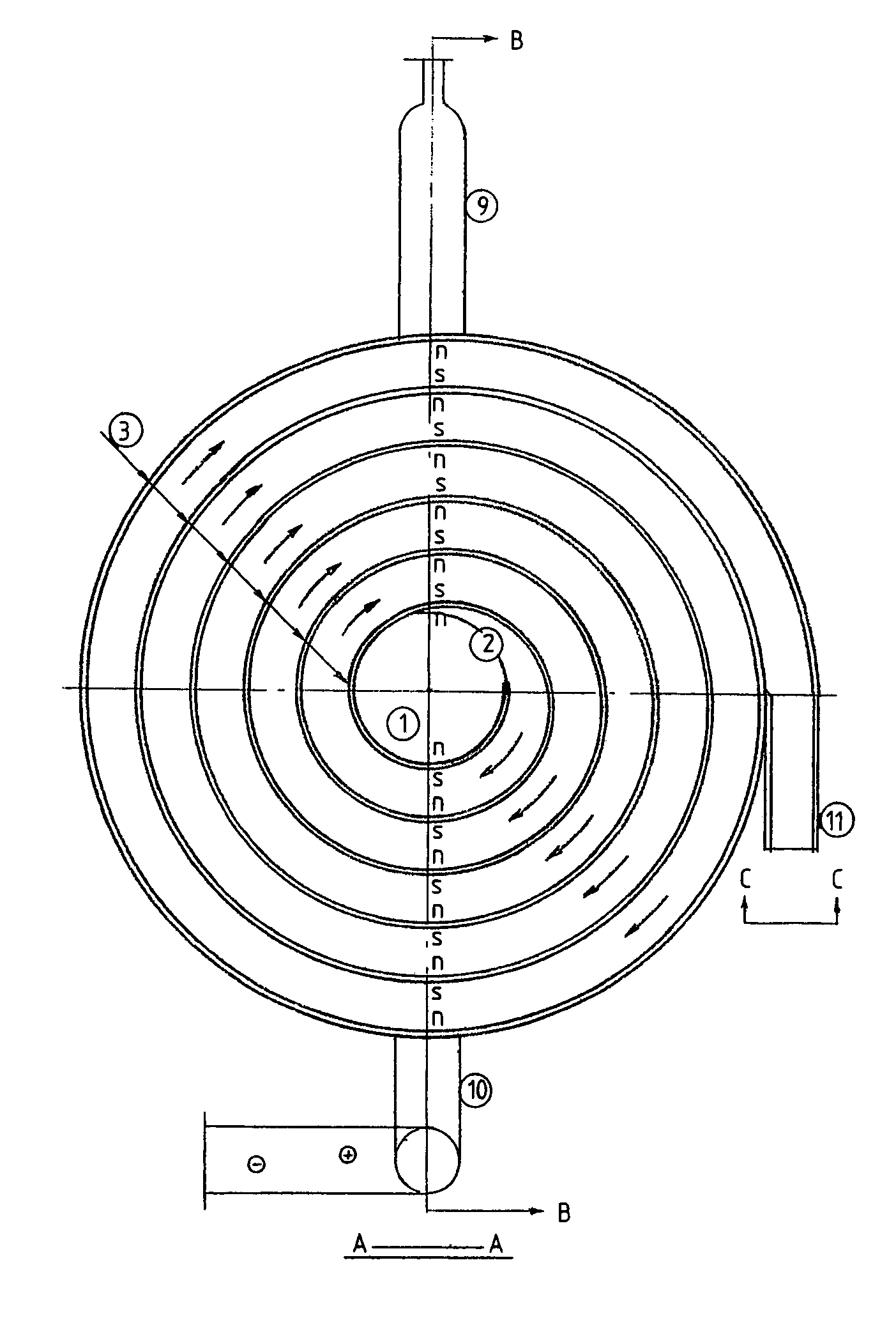
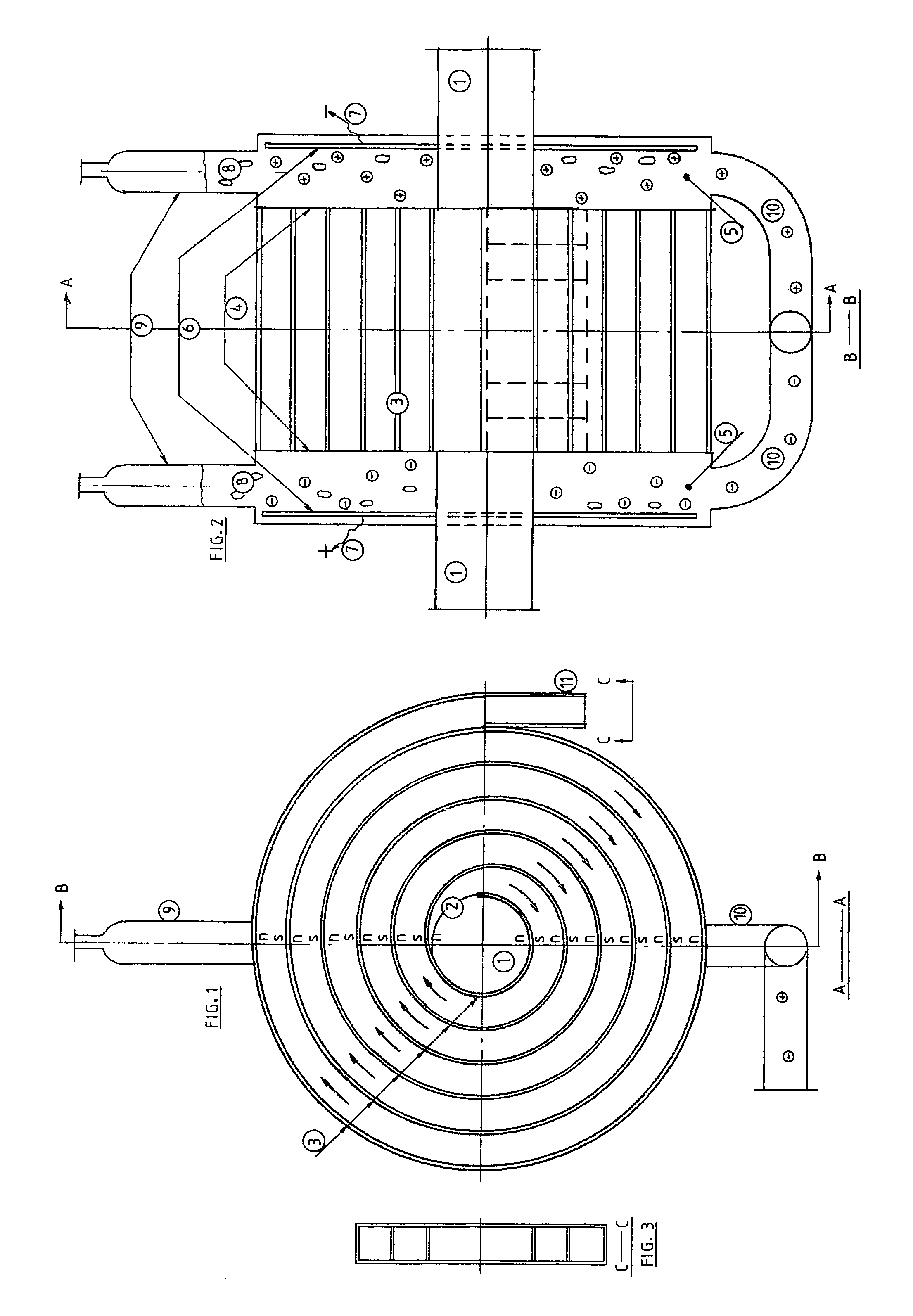
[0012]FIG. 1 and FIG. 2 show the inlets (1) into the spiral conduit with the possibility (from two intakes) to supply the liquid to be treated to the center of the conduit; the spiral center with its outlet (2) into the spiral conduit; the spiral conduit wall (3) provided with magnets along its full length having their magnetic North (n) and South (s) poles in two adjacent conduit flow streams; the spiral open ends (4) with chambers (5) outside, where oppositely charged ions are collected; the electrodes (6) in the chambers to discharge ions with electric connections (7) to short-circuit the electrodes; gas bubbles (8) generated by the ion discharge in the electric circuit; collection bottles (9) in which the gases are collected; outlet pipes (10) of drain solution from the chambers; the spiral conduit outlet (11) with cells, FIG. 3; ions shown in circles with positive and negative charge.

DETAILED DESCRIPTION OF THE INVENTION

[0013]This invention is best exemplified by desalination ...


PUM

PropertyMeasurementUnit
Poweraaaaaaaaaa
Concentrationaaaaaaaaaa
Magnetic fieldaaaaaaaaaa

Abstract

This invention is applied to any ionized solution of dissolved solids and electrolytes, such as sea water, which is forced through a conduit equipped with a magnetic wall of rectangular cross-section, which induces a magnetic field, where ions separate when passing through according to magneto-hydrodynamic physics. The conduit is made up of one continuous magnetic wall, a spiral or similar, with opposite magnetic poles on each side, where these both sides co-operate to extend magnetic fields with parallell wall in the same direction through the whole conduit. The ionized solution is pumped into the center of the spiral and further out through the spiral or similar. The charged ions in the flow stream are deflected laterally towards the open ends and as separated positive or negative ions into chambers outside the conduit. The ions concentrating in each chamber influence an electric tension acting similar to a capacitor, which counteracts the magnetic field movement of the ions but is released by short-circuiting the electrodes placed in each chamber to discharge the ions thus inducing a useful current. With the discharge of ions gases are produced and trapped in cylindrical collectors. The spiral outlet is divided into cells to control and to adjust the degree of de-ionization. An additional power source connected in series with the electric circuit increases the rate of de-ionization and speeds up ion discharge and gas output. The effluents have a controlled speed outflow from both chambers into drainpipes.

Description

BACKGROUND[0001]The present invention is related to one of the most important challenges to mankind today—obtaining potable as well as distilled water from the sea. Although the invention can be applied to other commercial fields for the de-ionization of solutions and the extraction of ions to produce valuable gases, the primary goal is desalination of sea water. The world's number one user of water is agriculture for irrigation, which together with industry accounts for between 80 and 90% of world consumption. Sea water contains dissolved salts, mainly ions of sodium (Na+) and chlorine (Cl−), and is not useful. Some Middle Eastern countries, especially Saudi Arabia, have resources through their oil wealth but no water. Improved living standards and rapid increase in population require building of new desalination plants at huge costs. These desalination plants are powered by abundant sources of fossil fuels, oil and natural gas. The sea water is boiled and the steam is cooled to pr...

Claims


Application Information

Patent Timeline
IPC IPC(8): C02F1/48H02K44/14B03C1/32C02F1/46
CPCB03C1/32C02F1/4604C02F1/48C02F1/4608C02F2301/026C02F2103/08
Inventor HARDE, NILS YNGVE
Owner HARDE CHRISTINA
Learn More