
Dual fiber optic amplifier with shared pump source

a technology of pump source and fiber optic amplifier, which is applied in the direction of lasers, electromagnetic transmission, transmission, etc., can solve the problems of reducing the total cost of the pump source, affecting the overall cost of the amplifier, and affecting the signal being transmitted through the fiber optic system. , to achieve the effect of reducing the total power used, significantly reducing the cost of the power amplifier and the pre-amplifier associated with the transceiver

Active Publication Date: 2006-04-18
II VI DELAWARE INC
View PDF3 Cites 14 Cited by
  • Summary
  • Abstract
  • Description
  • Claims
  • Application Information

AI Technical Summary

Benefits of technology

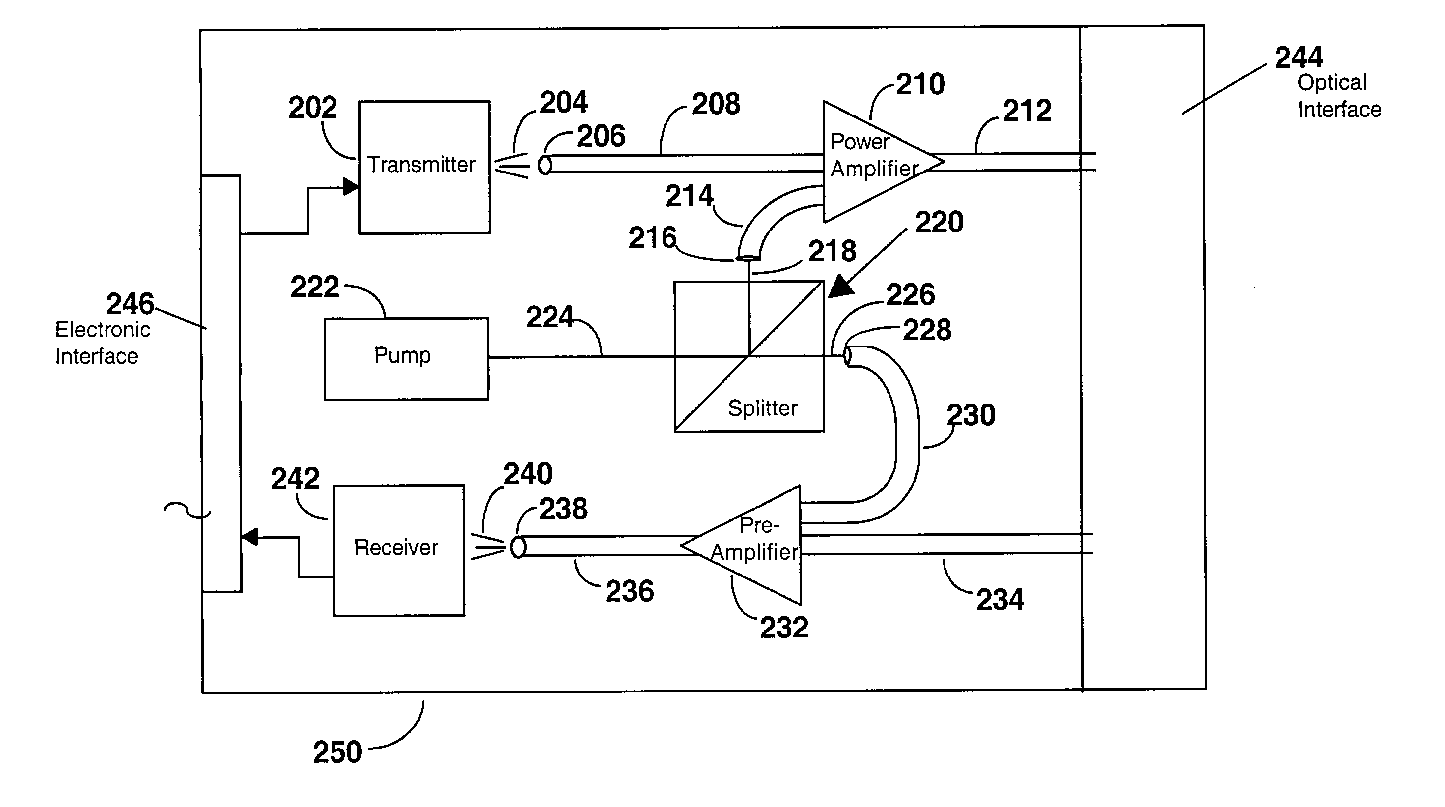
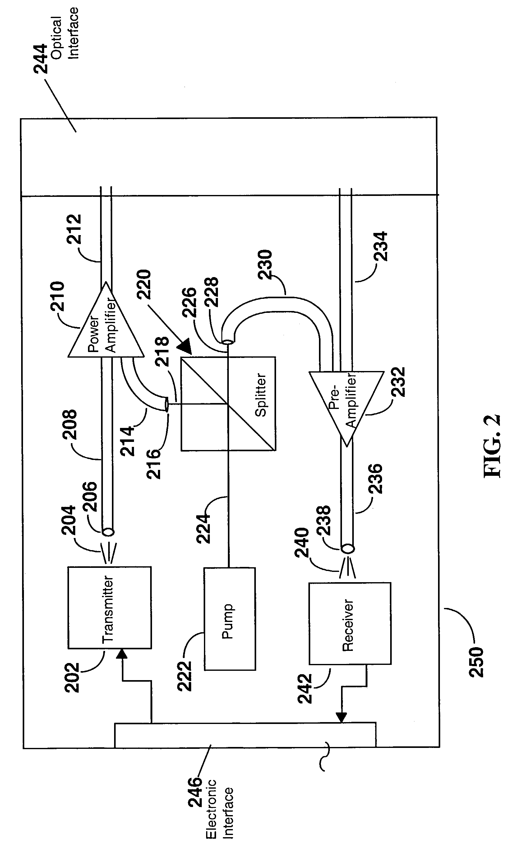
[0011]By cutting the number of pump sources in half, the total cost of the power amplifier and pre-amplifier associated with a transceiver is significantly lowered. Replacing two pump sources with one also typically reduces the total power used by the amplifiers in the transceiver, and enables the transceiver to be placed in a smaller housing. Thus, it is highly desirable to use one pump source for both the power amplifier and pre-amplifier.

Problems solved by technology

A signal being transmitted through a fiber optic system may suffer amplitude attenuation due to energy absorption, beam scattering and other processes during transmission.
The cost of the pump sources is often a significant part of the total cost of the amplifiers.
However, metropolitan area networks (MANs) tend to have shorter distances between transceivers and are more cost sensitive than long distance telecommunications systems.
As such, the considerable expense of multiple pump sources is relatively more significant for metropolitan area networks.

Method used


Image

  • Dual fiber optic amplifier with shared pump source
  • Dual fiber optic amplifier with shared pump source
  • Dual fiber optic amplifier with shared pump source

Examples


Embodiment Construction

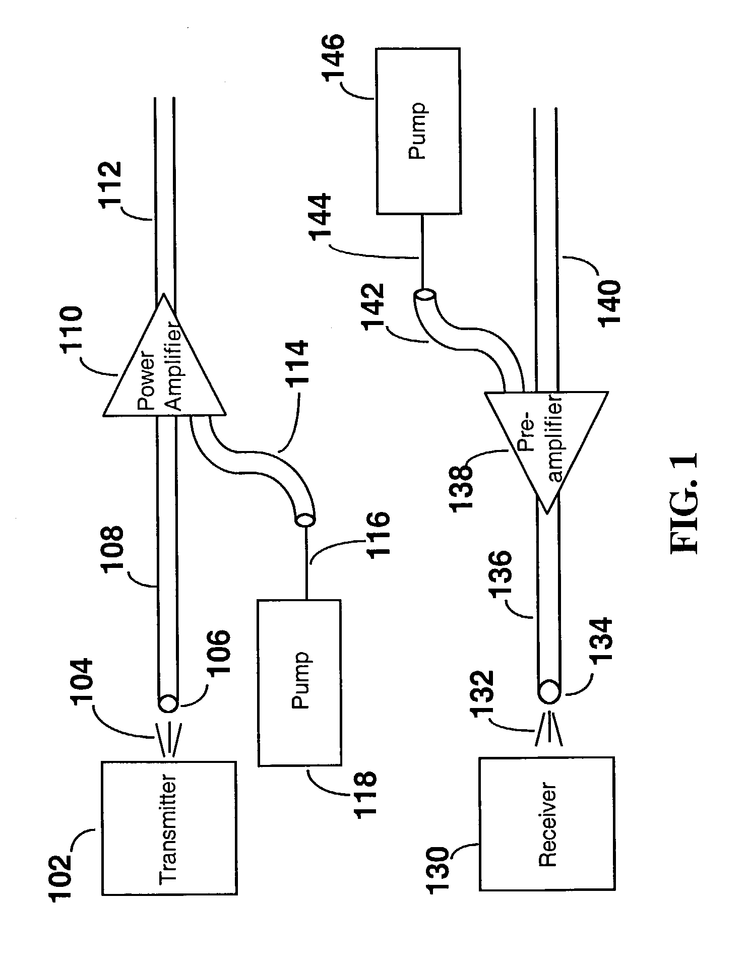
[0020]Referring to FIG. 1, there is shown an example of the conventional approach to multiple optical power amplifiers used in conjunction with transceivers or a set of transmitters and receivers that are relatively close to each other. Two separate pump sources 118, 146 are used—one for each of the optical power amplifiers 110, 138. The two optical power amplifiers are a power amplifier 110 and a pre-amplifier 138.

[0021]Each of the optical power amplifiers 110, 138 is a doped fiber amplifier that includes a length of optical fiber that has been doped with certain elements. Such amplifiers amplify an optical signal, if the signal is within a particular wavelength range, when the doped fiber receives optical energy from a pump source. Such amplifiers produce amplification by stimulated emission—the dopants in the doped fiber are stimulated to a higher energy state by receiving pump power and may achieve a population inversion. As energy falls back to lower energy levels additional ph...


PUM


Abstract

A dual fiber optic amplifier uses a single pump source for two or more optical power amplifiers. The dual fiber optic amplifier includes a pump source that emits light, a pump splitter, a first optical power amplifier and a second optical power amplifier. The pump splitter splits the light emitted by the pump source into two or more portions. The first optical power amplifier includes an optical fiber input, an optical fiber output, and a doped fiber portion, wherein the first portion of light from the splitter is coupled into the optical fiber input of the first optical power amplifier. The second optical power amplifier includes an optical fiber input, an optical fiber output, and a doped fiber portion, wherein the second portion of light emitted from the splitter is coupled into the optical fiber input of the second optical power amplifier.

Description

[0001]This application claims the benefit of Provisional App. No. 60 / 422,599, filed Oct. 31, 2002.[0002]The present invention relates generally to a system for pumping optical energy into doped fiber optical amplifiers, and particularly to a system using a single pump source to provide optical energy to more than one doped fiber optical amplifier.BACKGROUND OF THE INVENTION[0003]Fiber optic communication utilizes optical transmitters, optical receivers and optical fiber, among other components, to transmit light signals through the fiber. The transmitters and receivers are often integrated into a single component called a transceiver. Transmitters are light sources, such as lasers or light-emitting diodes. Receivers usually include a photo detector.[0004]A signal being transmitted through a fiber optic system may suffer amplitude attenuation due to energy absorption, beam scattering and other processes during transmission. To compensate for such signal loss during transmission, opti...

Claims


Application Information

Patent Timeline
IPC IPC(8): H04B10/12H01S3/00H01S3/067H01S3/094H04B10/17
CPCH01S3/06758H04B10/2918H01S3/094003H01S3/094061H04B10/298
Inventor LIU, JIANWANG, ZHENGHUANG, YONGLINLU, XUEJUN
Owner II VI DELAWARE INC
Learn More