
Programmable calibration circuit for power supply current sensing and droop loss compensation

a technology of droop loss compensation and power supply current sensing, which is applied in the direction of electric controllers, instruments, dynamo-electric converter control, etc., can solve the problems of inefficient and expensive sense resistors, insufficient operation, and excessive heat in power devices of one or more phases, so as to reduce chip waste and minimize waste

Active Publication Date: 2006-04-11
TABAIAN FEREYDUN
View PDF18 Cites 40 Cited by
  • Summary
  • Abstract
  • Description
  • Claims
  • Application Information

AI Technical Summary

Benefits of technology

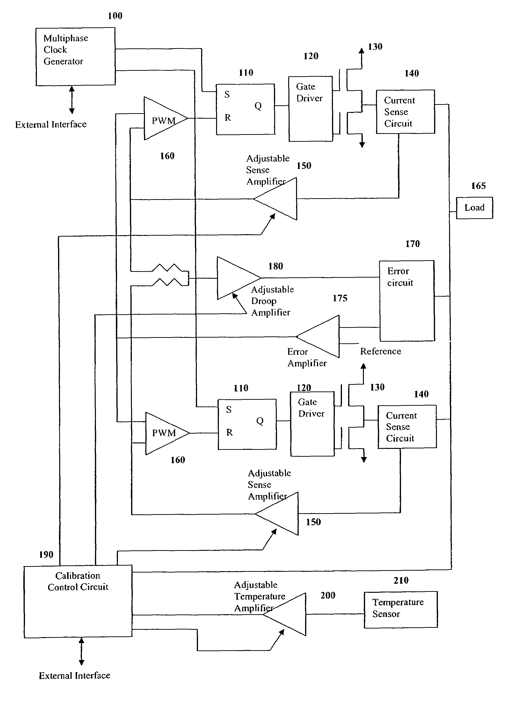
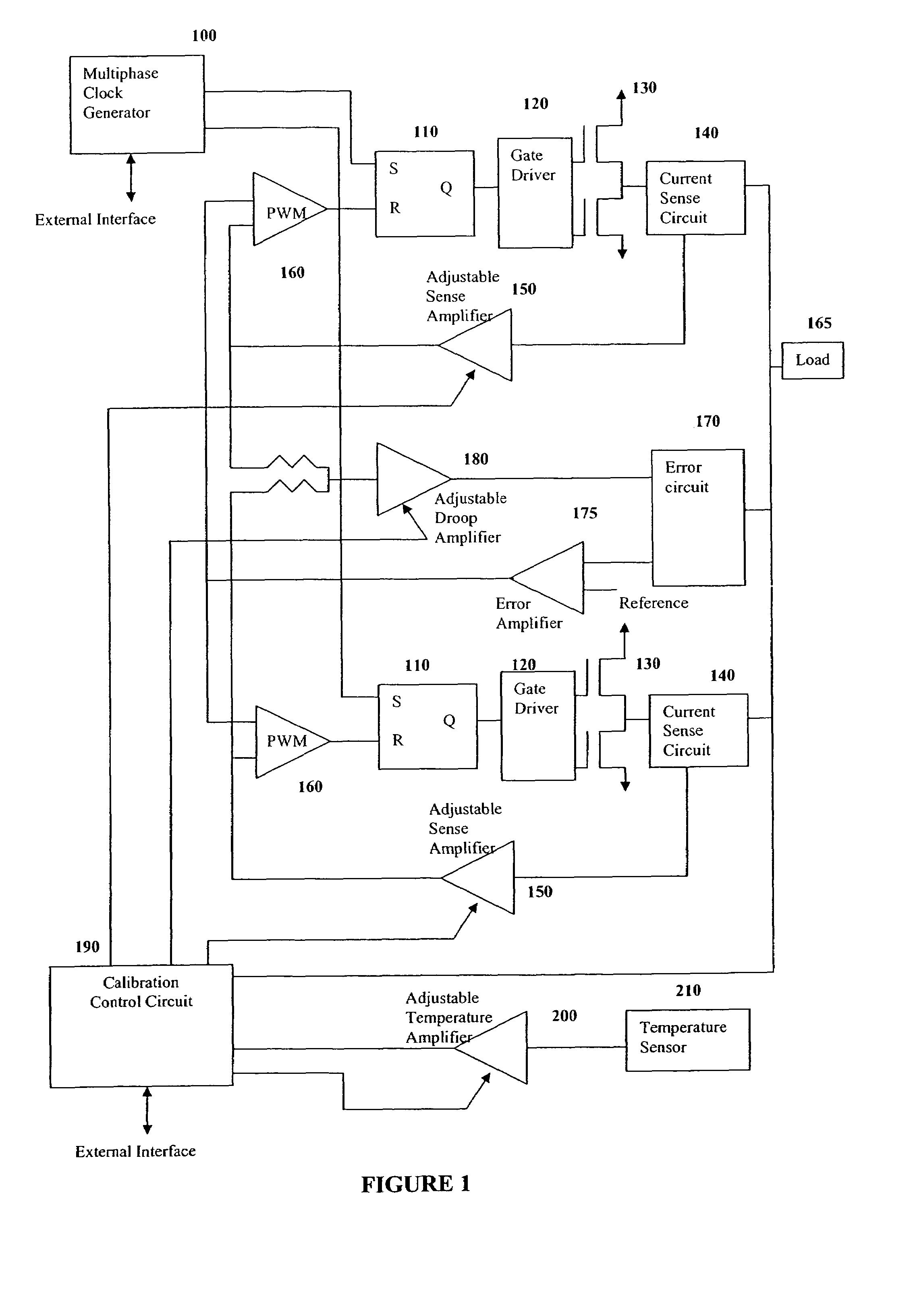
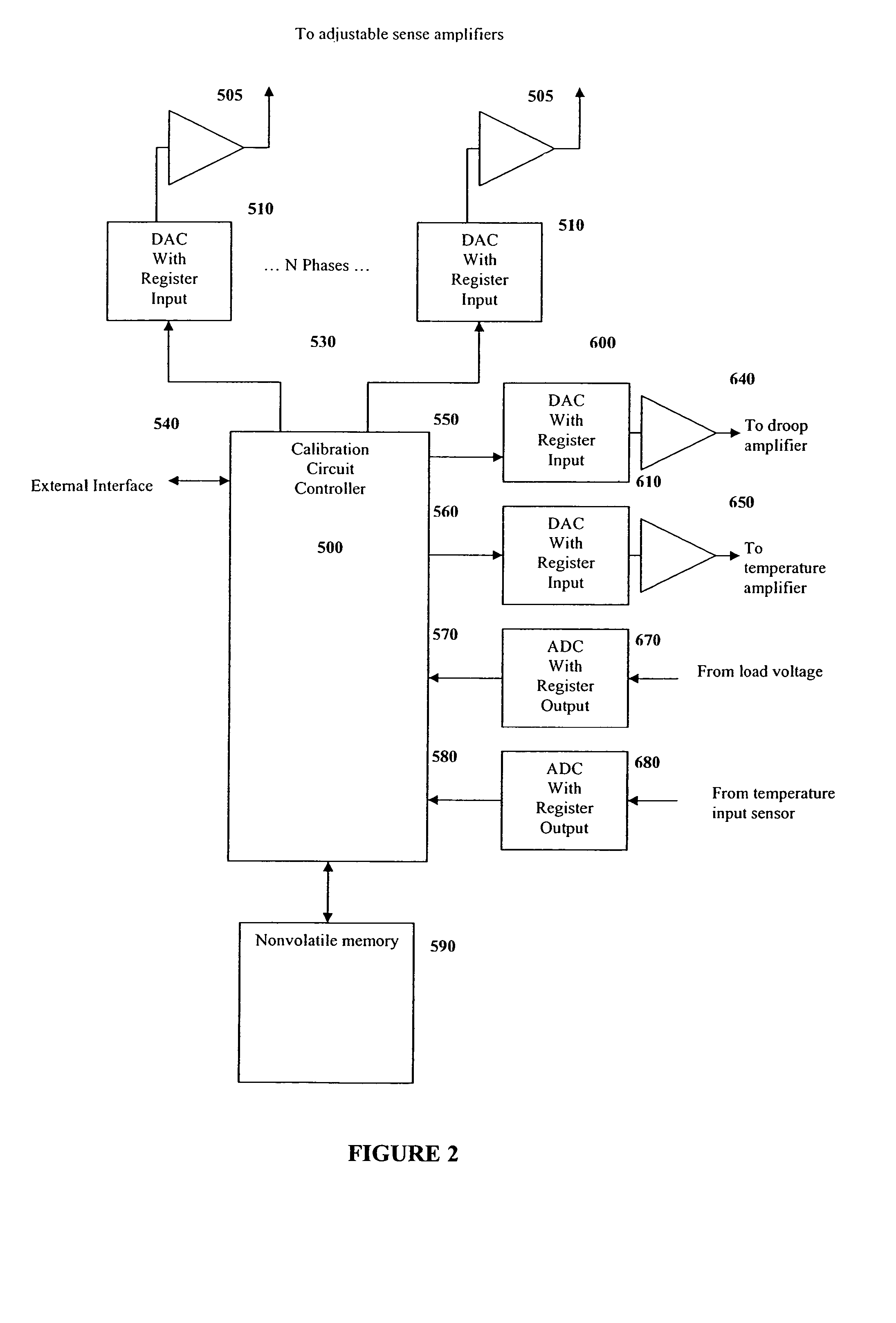
"The present invention relates to a circuit that includes a regulator circuit and a calibration control circuit. The calibration control circuit includes a controller, a nonvolatile memory, droop outputs, sense outputs, and a temperature input. The calibration control circuit adjusts the droop outputs and sense outputs based on data stored in the nonvolatile memory. The circuit can calibrate the calibration control circuit based on data stored in an external controller or an internal controller. The calibration control circuit can also adjust the droop amplifier to compensate for variations in the regulator circuit. The technical effect of the invention is to provide a more efficient and accurate circuit for regulating power and adjusting the load voltage and temperature of a circuit."

Problems solved by technology

Due to discrete components and power device mismatches, the load current is not always equally shared among all the phases of multi-phase regulators causing inadequate operation and excessive heat in the power devices of one or more phases of a multi-phase power supply.
Since sense resistors are both inefficient and expensive, other resistive elements such as RDSon of the power MOSFETs, DCR of the inductor, and board traces are used to measure the source current for each phase of the power supply.
Historically, using these elements to sense current causes a mismatch in the current between the phases.
Currently there are no reasonable solutions to this mismatch.
Historically, setting the droop accurately has also been a major problem due to inadequacies in current sensing and processor batch variations.
Presently, the droop setting is fixed, thus once the system has been built, the droop rate cannot be changed without overly costly retrofits.
Because the droop setting is fixed, the power supply is unable to adapt to the processors power needs.
Therefore, processors with power specifications beyond what the power supply can produce are wasted.
This processor waste is very inefficient and costly.
This variation results in erroneous measurements of the current over temperature variations causing further droop inaccuracies.

Method used


Image

  • Programmable calibration circuit for power supply current sensing and droop loss compensation
  • Programmable calibration circuit for power supply current sensing and droop loss compensation
  • Programmable calibration circuit for power supply current sensing and droop loss compensation

Examples


Embodiment Construction

[0029]It is to be understood that the present invention is not limited to the particular methodology, compounds, materials, manufacturing techniques, uses, and applications, described herein, as these may vary. It is also to be understood that the terminology used herein is used for the purpose of describing particular embodiments only, and is not intended to limit the scope of the present invention. It must be noted that as used herein and in the appended claims, the singular forms “a,”“an,” and “the” include the plural reference unless the context clearly dictates otherwise. Thus, for example, a reference to “an element” is a reference to one or more elements and includes equivalents thereof known to those skilled in the art. Similarly, for another example, a reference to “a step” or “a means” is a reference to one or more steps or means and may include sub-steps and subservient means. All conjunctions used are to be understood in the most inclusive sense possible. Thus, the word ...


PUM


Abstract

A circuit for regulating power is disclosed. The present invention provides circuits and methods for current sensing variations, static droop settings, mismatched phase outputs, and temperature variations in a multiphase power regulator. The circuits may include a calibration controller that senses and regulates both a current sensing circuit and the droop in a power regulator over a range of temperatures thus equalizing phase outputs. The present invention includes the schematic organization and implementation of the circuit, the circuit's calibration, its use, and implementation. This invention advantageously provides circuits and methods to properly power a processor or IC chip according to the unique power specifications of the processor or chip.

Description

CROSS-REFERENCE TO RELATED APPLICATIONS[0001]This application claims the benefit, under 35 U.S.C. §119, of U.S. provisional Application Ser. No. 60 / 484,105, filed 30 Jun. 2003, the entire contents and substance of which is hereby incorporated by reference.BACKGROUND OF THE INVENTION[0002]Multi-phase voltage regulators are commonly used over single-phase regulators because they produce higher current output, faster transient responses, and more efficient applications in microprocessor power supplies. Due to discrete components and power device mismatches, the load current is not always equally shared among all the phases of multi-phase regulators causing inadequate operation and excessive heat in the power devices of one or more phases of a multi-phase power supply. To overcome this problem, active current sharing may be utilized to force current equalization among all phases. This requires a current sensing circuit. Since sense resistors are both inefficient and expensive, other res...

Claims


Application Information

Patent Timeline
Patent Type & Authority Patents(United States)
IPC IPC(8): G01R35/00G05B11/01G05D3/12G05D11/00G05F1/56
CPCH02P23/0077H02M3/1584H02M1/327
Inventor TABAIAN, FEREYDUNHEJAZI, ALISADATI, HAMEDASHRAFZADEH, AHMAD
Owner TABAIAN FEREYDUN
Learn More