Automatic transmission

a transmission and automatic technology, applied in mechanical equipment, transportation and packaging, gear shifting, etc., can solve the problems of reducing the driving speed, affecting the transmission response ability, and the driver may feel uncomfortable, so as to reduce the shock of the gear shift, improve the response ability of the transmission, and smooth the effect of the gear shift quality

Inactive Publication Date: 2006-04-04
SUBARU CORP
View PDF8 Cites 25 Cited by
  • Summary
  • Abstract
  • Description
  • Claims
  • Application Information

AI Technical Summary

Benefits of technology

[0021]In accordance with an automatic transmission of the present invention, it is possible to considerably reduce a gear shift shock so as to achieve a smooth gear shift quality by arranging a plurality of bypass clutches between the engine and the input shaft and properly using the bypass clutch for carrying out the torque transmission in correspondence to the transmission gear range. When shifting the gears, it is possible to carry out a jumped (or skipped) gear shift at the driver's discretion by engaging the bypass clutch only for a predetermined time, and it is possible to improve a response ability of the transmission, whereby a sporty gear shift can be achieved.
[0022]Since a start clutch and a plurality of the bypass clutches are continuously arranged in series at an end portion of the input shaft, it is possible to secure an improved mountability while avoiding the transmission from being large in size and long, it is possible to use common elements of the automatic and manual transmissions, and it is possible to more improve the design freedom in a layout of the main components.
[0023]Further, since the input and bypass clutches are continuously arranged in series at the end portion of the input shaft, it is possible to synthetically supply a fluid or a lubricating oil for operating the respective clutches, and it is possible to improve a gear shift response.

Problems solved by technology

Thus, the driver feels the driving speed reduced as well as torque loss during the gear shift, so that the driver may feel uncomfortable.
And the gear ratio difference is large between this speed and the second speed even by adding the torque increase generated by an inertia moment in the input side of the bypass clutch, so that it is impossible to sufficiently compensate the difference in the driving force change between the both.
If the difference is large, not only the gear shift shock is generated so as to cause a reduction in a gear shift quality of the automatic transmission, but also the torque is reduced during the gear shift even when an acceleration is required, so that the driver feels uncomfortable.
In the same manner, when shifting the gears from the second speed to the third speed, it is also impossible to sufficiently compensate the difference between the transmission torque transmitted via the bypass clutch and the drive force change caused by the gear shift ratio difference from the second speed to the third speed, even by adding the torque increase generated by the inertia moment mentioned above, so that a gear shift shock is generated and a gear shift quality reduction is caused.
In this case, since the speed increase and the speed reduction are carried out while passing via the transmission gear range on the way, there are generated problems such that a time for shifting gears becomes generally long, the driver feels a stress in the gear shift during an acceleration for passing over, and the like.
On the contrary, since the structure of the transmission gear train is the structure which is clearly classified into the odd range train group and the even range train group, there is generated a problem that a design freedom is not obtained in the arrangement of the gears in the transmission main body and the layout of the operation system.
In particular, if it is desired to wholly and appropriately use the basic structure of the manual transmission, there is generated the problem that the same mechanism can be used only by arranging the manual transmission in such a manner that the transmission gear trains are separated into the even transmission gear trains and the odd transmission gear trains.

Method used


Image

  • Automatic transmission
  • Automatic transmission
  • Automatic transmission

Examples


Embodiment Construction

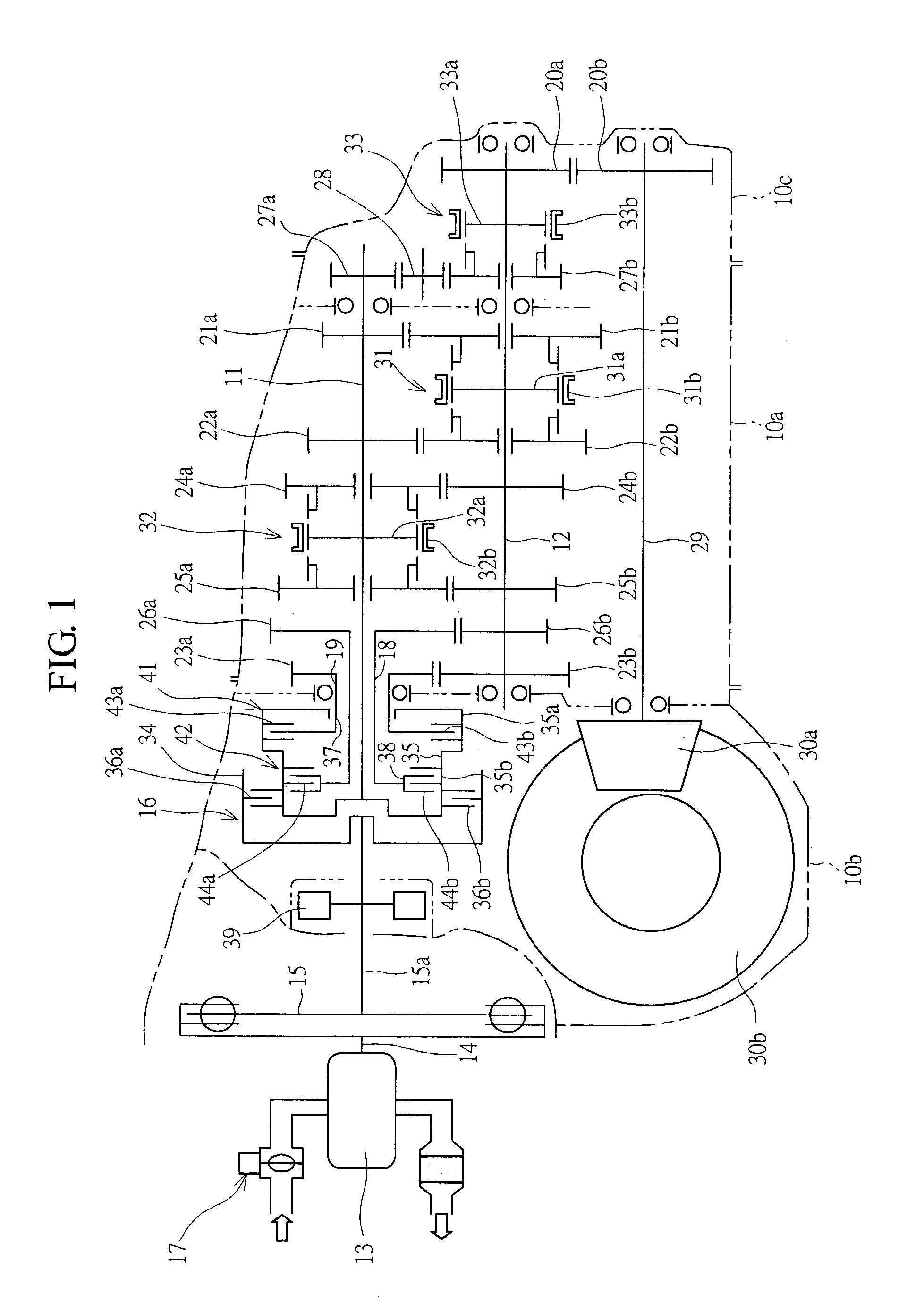
[0030]As shown if FIG. 1, an automatic transmission has an input shaft 11 and an output shaft 12, and these shafts 11, 12 are contained within a transmission case 10a so as to be in parallel with each other. A clutch case 10b is mounted on one end side of the transmission case 10a, and an extension case 10c is mounted on another end side thereof.

[0031]A damping (or attenuating) apparatus, that is, a damper 15 is arranged between a crankshaft 14 and an input shaft 11 of an engine 13. And an input clutch, that is, a start clutch 16 is arranged between the damper 15 and the input shaft 11. Accordingly, when the start clutch 16 is in an engaged state, an engine power is damped in vibration by the damper 15 so as to be transmitted to the input shaft 11, and the engine power is not transmitted by releasing the engagement. Further, the start clutch 16 is formed by a multiple disc type wet friction clutch, and has a function of forming a half-clutch state, that is, a slip state so as to smo...


PUM


Abstract

An automatic transmission with input shaft having drive gears and an output shaft with driven gears engaging with the drive gears are provided. A transmission gear for transmitting a power is selectively switched from transmission gear trains of the drive gears and driven gears, by a switching mechanism. An input clutch for switching engine power transmission and input shaft disconnect states is arranged between an engine crankshaft and the input shaft. Bypass clutches capable of transmitting the power to the respective transmission gear trains are provided at an end portion of the input shaft, and the engine power is transmitted to the output shaft via at least any one of the bypass clutches at a time of shifting gears. The input clutch and the plurality of bypass clutches are concentrically arranged in series between the engine and the input shaft providing size reduction.

Description

TECHNICAL FIELD OF THE INVENTION[0001]The present invention relates to an automatic transmission mounted on a vehicle, and more particularly to an automatic transmission having a plurality of transmission gear trains, which are easily selective as required for any driving conditions thereof.BACKGROUND OF THE INVENTION[0002]A manual transmission (MT) carrying out a gear shift operation manually has an input shaft to which a plurality of drive gears are provided, and an output shaft to which a plurality of driven gears forming transmission gear trains together with the drive gears are provided. An engine power is input to the input shaft via an input clutch, and the output shaft is connected to a drive wheel. In this MT, a gear shift operation, that is, a shift change is carried out by disconnecting the input clutch for changing gears, thereafter switching by an engagement clutch such as a synchro-mesh mechanism or the like into one of the gear trains to carry out the power transmissi...

Claims


Application Information

Patent Timeline
Patent Type & Authority Patents(United States)
IPC IPC(8): F16H3/08B60K17/02F16H3/00F16H3/089
CPCF16H3/006Y10T74/19242Y10T74/19228
Inventor KOBAYASHI, TOSHIO
Owner SUBARU CORP
Why Eureka
Try Eureka