
Circuit board capacitor structure for forming a high voltage isolation barrier

Inactive Publication Date: 2006-03-21
SYNAPTICS INC
View PDF9 Cites 73 Cited by
  • Summary
  • Abstract
  • Description
  • Claims
  • Application Information

AI Technical Summary

Benefits of technology

[0019]Briefly, the present invention relates to a circuit board capacitor structure capable of being used as a high voltage isolation barrier in communication circuitry. The capacitor structure can be flexibly arranged to maximize use of board space, and results in a reduced number of relatively expensive discrete components.
[0023]A capacitive structure implemented in accordance with the present invention thus allows usage of circuit board space to be optimized, and provides a cost effective alternative to the discrete capacitors used in prior communication circuits.

Problems solved by technology

More particularly, telephone line voltages may vary widely across a given network, and often exceed the operating voltage of subscriber equipment.
While the isolation transformer of a DAA protects the electronic components of a modem, it often introduces distortion and consumes a relatively large amount of space.
In today's world of ever-shrinking electronics, the bulk of the isolation transformer may govern the physical dimensions of the modem itself and impose other unwanted constraints on cost sensitive modem circuitry.
Although enabling the use of smaller and lighter isolation transformers, this configuration may result in excessive distortion.
This type of isolation, however, may suffer from distortion, cost and complexity issues.
Thermal and resistive isolation techniques have also been employed, but are typically complex and expensive to manufacture.
The requirement of passing analog audio signals across the high voltage isolation barrier for provision to a coder / decoder (CODEC) and other DAA circuitry hampers efforts to decrease the size and cost of the barrier due to the foregoing design constraints.
Further, each signal path across the barrier adds to size and expense of the high voltage isolation barrier.

Method used


Image

  • Circuit board capacitor structure for forming a high voltage isolation barrier
  • Circuit board capacitor structure for forming a high voltage isolation barrier
  • Circuit board capacitor structure for forming a high voltage isolation barrier

Examples


Embodiment Construction

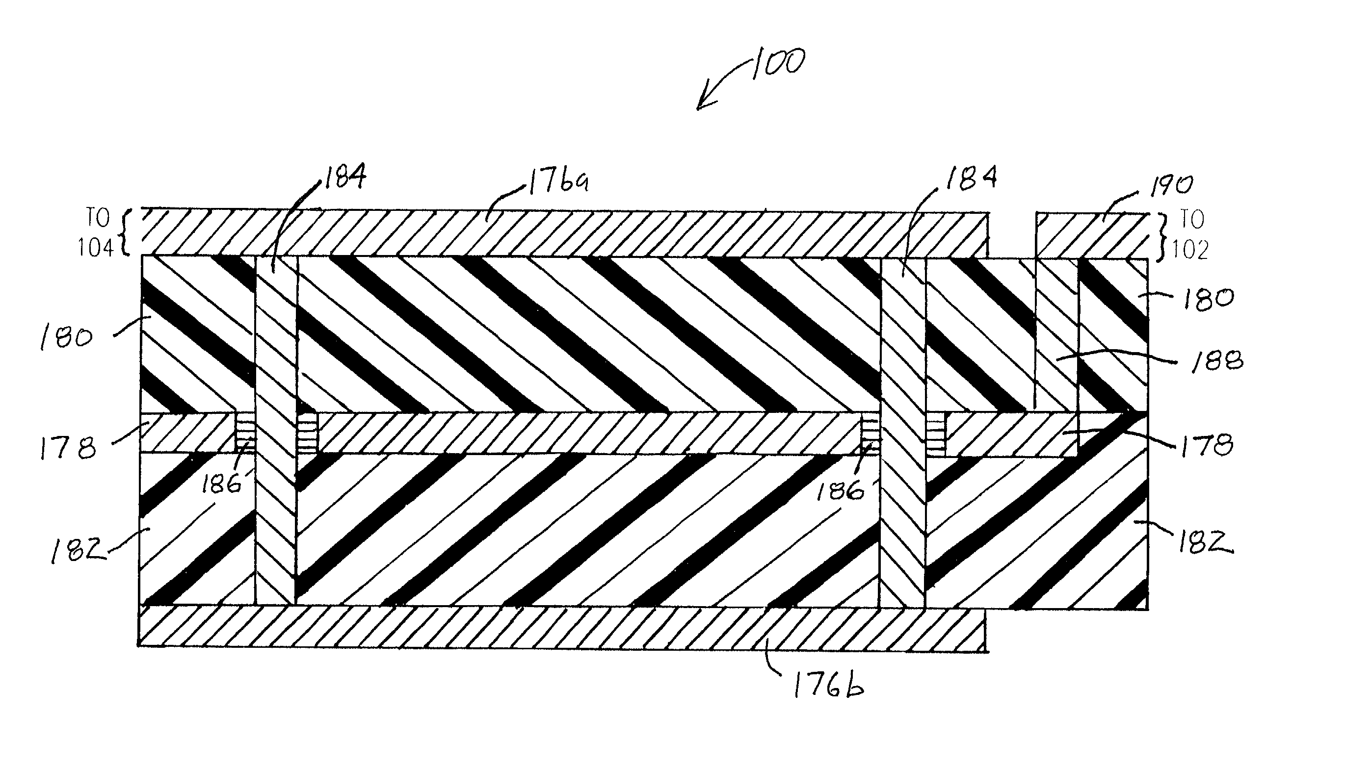
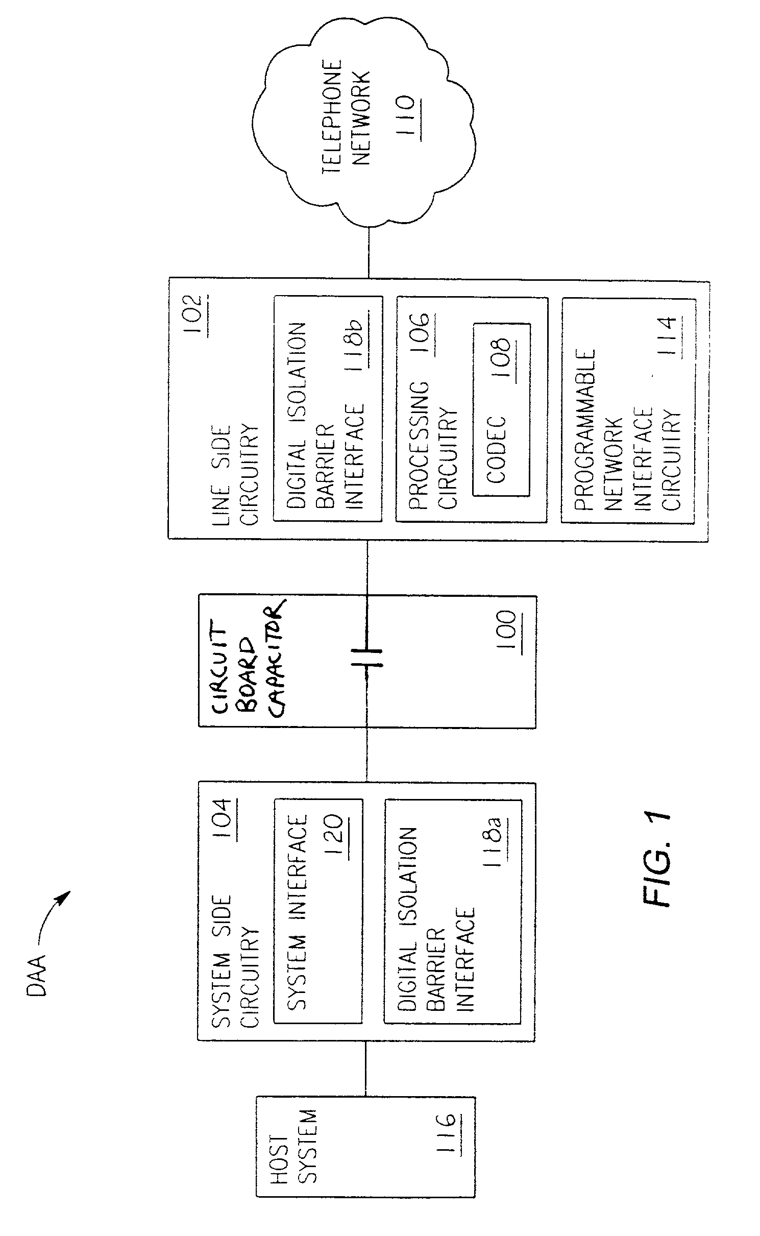
[0032]FIG. 1 is a block diagram of a Data Access Arrangement (DAA) utilizing an exemplary circuit board capacitor structure 100 implemented in accordance with the present invention. In the illustrated embodiment, the circuit board capacitor 100 functions as a high voltage isolation barrier, although many other uses are contemplated. The circuit board capacitor 100 permits optimal usage of circuit board space, and provides a cost-effective alternative to the discrete capacitors used in prior communication circuits.

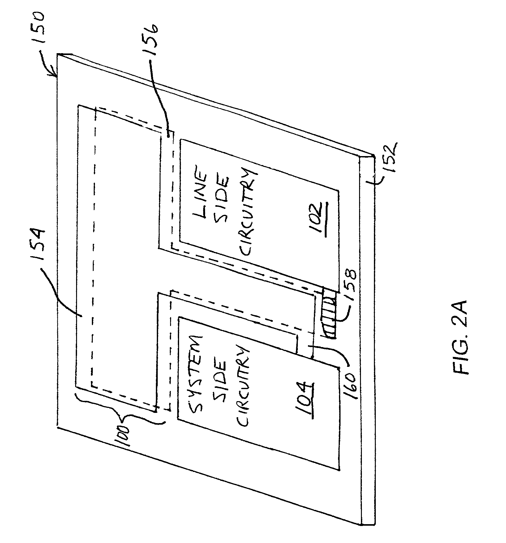
[0033]In one embodiment of the invention discussed below, the circuit board capacitor 100 is created by forming capacitor electrodes directly on opposing sides of a printed circuit board. The substrate of the printed circuit board intermediate the electrodes functions as a dielectric material to complete the capacitive structure. The electrodes of the capacitor are sized such that the area of the electrodes and the dielectric constant of the dielectric material result in th...


PUM


Abstract

A circuit board capacitor structure operable as a high voltage isolation barrier in communication circuitry. Capacitor electrodes form a capacitive structure directly on a printed circuit board's opposing sides. The PCB substrate intermediate the electrodes functions as the capacitive structure's dielectric material. The capacitor electrodes are sized such that the electrodes' area and the substrate's dielectric properties create the desired capacitance. Alternatively, a multi-layered PCB may be utilized where layer(s) is / are used to form the capacitive structure. The circuit board capacitor may couple communication circuitry located on the PCB's various sides. The circuit board capacitor operates as a high voltage isolation barrier in data access arrangements, separating line and system side circuitry. Further, the high voltage isolation barrier may include multiple circuit board capacitors to realize differential communications and / or multiple datapaths. The capacitor structure can be flexibly arranged to minimize PCB real estate and be more cost-effective than discrete capacitors.

Description

CROSS REFERENCE TO RELATED APPLICATIONS[0001]The following U.S. patent applications are hereby incorporated herein by reference in their entirety and made part of the present U.S. patent application for all purposes:[0002]U.S. patent application Ser. No. 09 / 193,222, entitled “Modem Having a Digital High Voltage Isolation Barrier,” filed Nov. 16, 1998.[0003]U.S. patent application Ser. No. 09 / 290,524, entitled “Multifunction Data Access Arrangement,” filed Apr. 12, 1999.[0004]1. Field of the Invention[0005]The present invention relates generally to communication devices for coupling to an external communication medium; and, more particularly, it relates to printed circuit board capacitor structure for use as a high voltage isolation barrier.[0006]2. Related Art[0007]Communication devices coupled to a telephone line or similar transmission medium generally must adhere to rigid electrical isolation requirements. Subscriber equipment or data communications equipment (DCE), such as data ...

Claims


Application Information

Patent Timeline
IPC IPC(8): H04M1/00H04M9/00H04M9/08H05K1/00H05K1/02H05K1/16
CPCH04L25/0266H05K1/162H05K1/0254H05K2201/09972H05K2201/09672H05K1/0298
Inventor BEUTLER, THOMAS GREYRAHAMIM, RAPHAEL
Owner SYNAPTICS INC
Learn More