
Linear electric motor

a technology of electric motors and electric motors, applied in the direction of positive displacement liquid engines, piston pumps, machines/engines, etc., can solve the problems of gas pressure through the suction valve of the compressor, and achieve the effect of reducing energy losses

Inactive Publication Date: 2006-03-21
EMPRESA BRASILEIRA DE COMPRESSORES SA (EMBRACO)
View PDF8 Cites 12 Cited by
  • Summary
  • Abstract
  • Description
  • Claims
  • Application Information

AI Technical Summary

Benefits of technology

[0008]It is an object of the present invention to provide a support for mounting the magnets to be used in a linear electric motor, said support using a small quantity of material and having such construction as to reduce the energy losses due to Foucault currents. It is another object of the present invention to provide a support, as cited above, for mounting the magnets used in a linear electric motor that drives the piston of a hermetic compressor of refrigeration.SUMMARY OF THE INVENTION
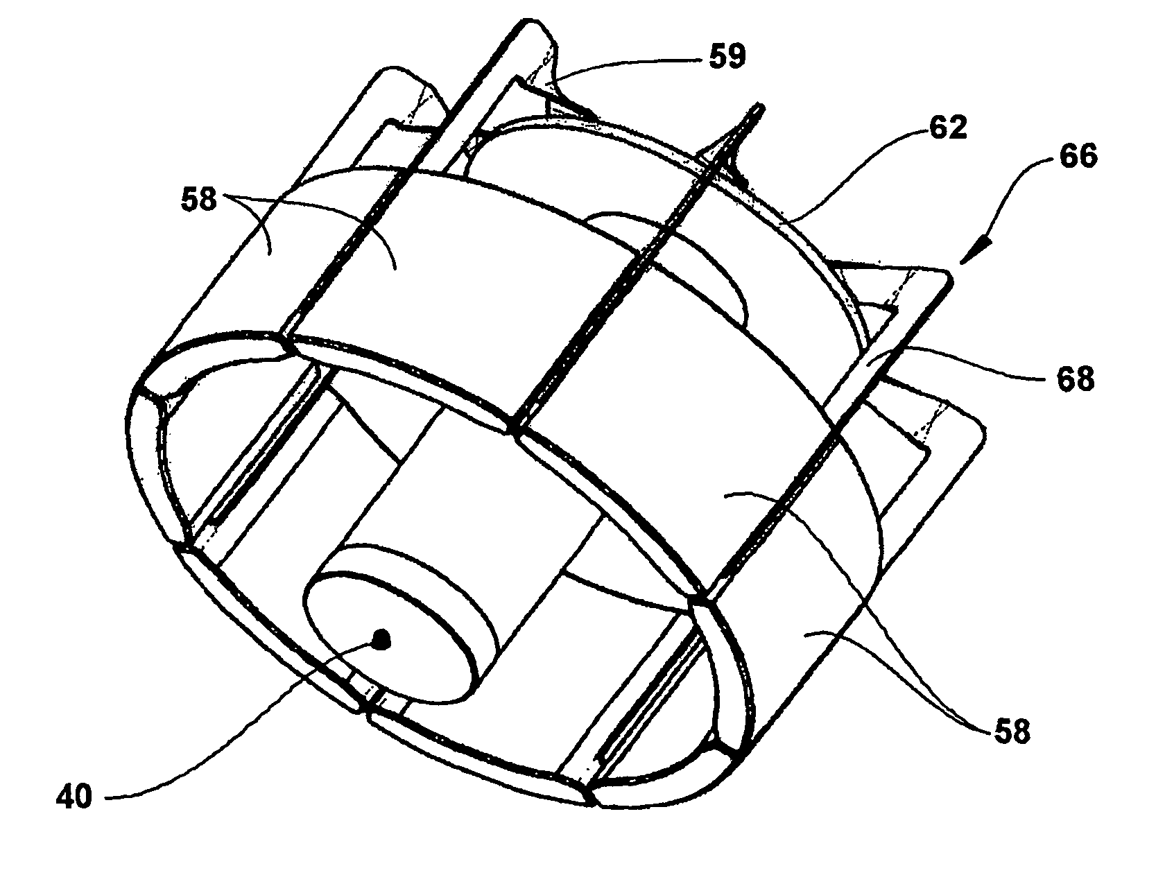
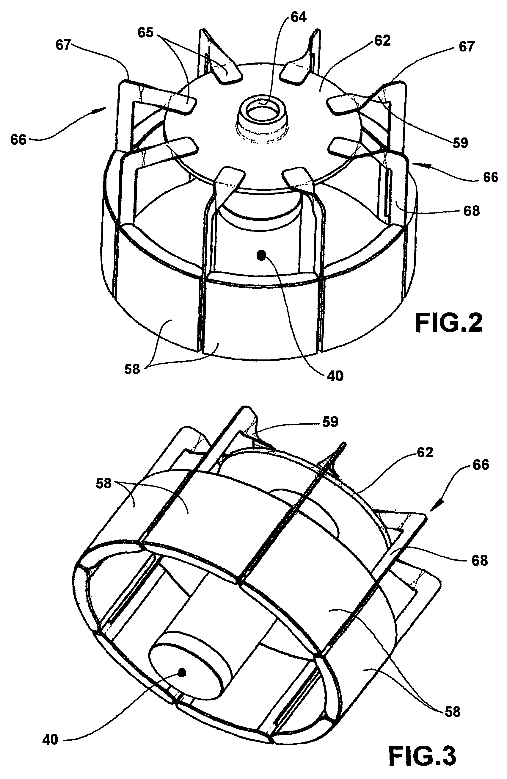
[0009]According to a preferred embodiment of the invention, a linear motor is used in a hermetic compressor of refrigeration to produce the reciprocating movement of a piston inside a cylinder, in order to compress the refrigerant gas. The coil of the electric motor is mounted to an internal wall of a block that forms the cylinder of the compressor, and a magnet support is mounted to a base flange of the piston extending outwardly from the contour of the latter. The magnet support is formed by a base plate mounted to the base flange of the piston and by a plurality of “L” shaped thin finger plates, which are spaced around and attached to the base plate, with the edges of the long legs of the finger plates extending radially of the central axis of the piston. An arcuate shaped permanent magnet is fitted between each pair of the long legs of the finger plates, in order to form a toroidal shaped magnet assembly that is stable and rigid.
[0011]The support structure of the present invention uses only flat plate material and in a small amount for defining the finger plates, which material can be of a relatively inexpensive type and with a configuration that reduces energy losses due to Foucault currents.

Problems solved by technology

When electric current is applied to the coil, the magnetic lines of force react with the permanent magnets of the toroidal structure to generate a force that produces linear displacement of the piston, thus resulting in compression of the gas admitted through the suction valve of the compressor.

Method used


Image

  • Linear electric motor
  • Linear electric motor
  • Linear electric motor

Examples


Embodiment Construction

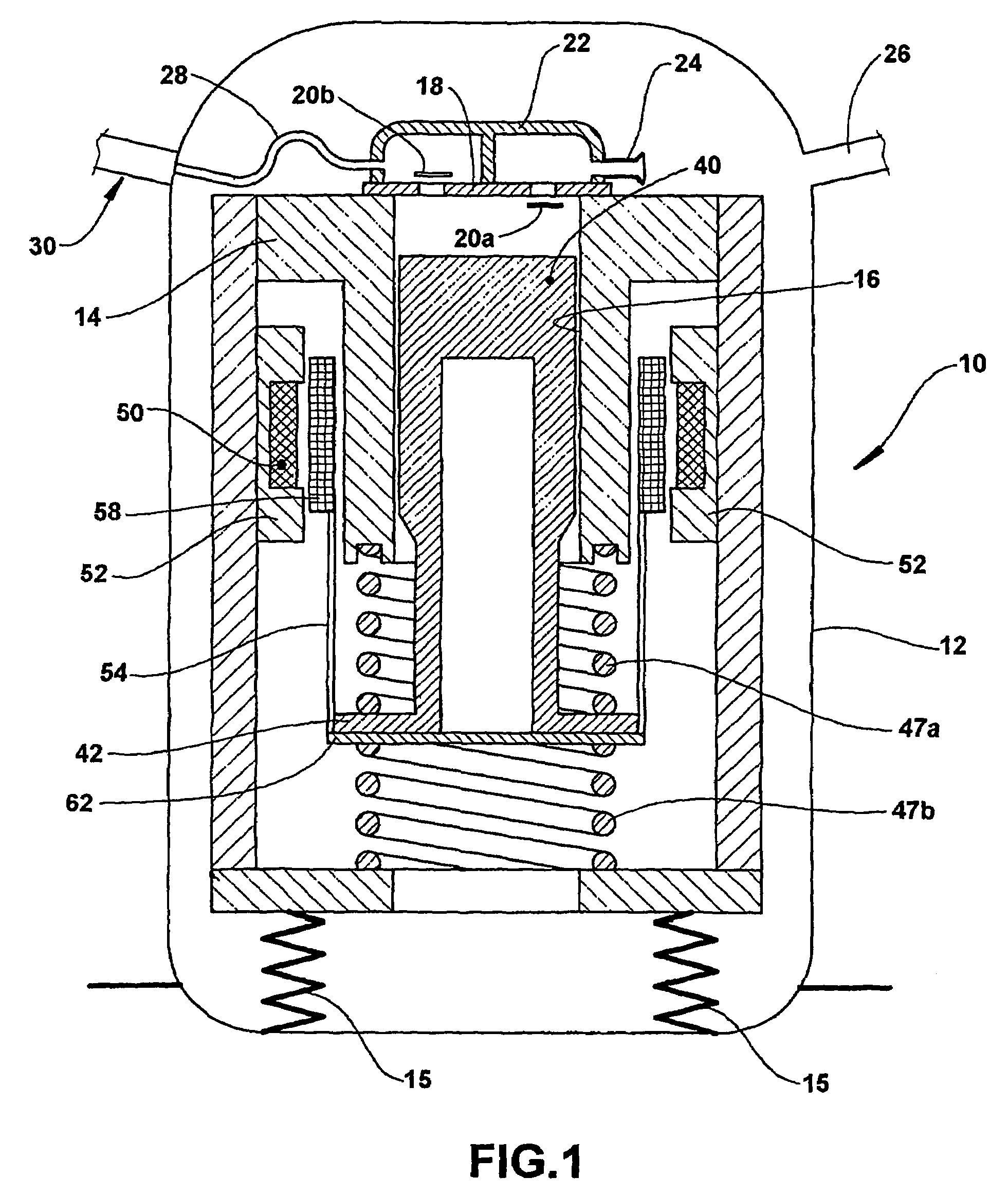
[0016]FIG. 1 shows a hermetic compressor 10 of the linear type for small refrigeration systems, having a hermetic shell 12, inside which is positioned a block 14 mounted to shock absorbers in the form of springs 15. Block 14 forms a cylinder 16 closed by a valve plate 18 on the cylinder head. A suction valve 20a and a discharge valve 20b are formed in the valve plate 18. The suction and discharge valves 20a and 20b control the admission and discharge of gas in relation to the cylinder. The valves are covered by a muffler 22 and there is an inlet duct 24 to the suction side of the muffler, and an outlet duct 28 from the discharge chamber of the muffler. The suction inlet to the hermetic shell 12 is shown at 26 and the outlet of compressed refrigerant gas from the hermetic shell is shown at 30.

[0017]The compression of the gas is produced by the axial movement of a piston 40 inside the cylinder 16. Piston 40 has a hollow interior and a base flange 42 at its end opposite to the valve pl...


PUM


Abstract

A linear electric motor, capable of producing reciprocation of a piston within a cylinder to compress refrigerant gas. The coil of the linear electric motor is mounted to the internal wall of a block that forms the cylinder of the compressor, and a support for the magnets is mounted to an outwardly extending base flange of the piston. The support is formed by a base plate mounted to the base flange with a plurality of “L” shaped finger plates spaced around and affixed to the base plate, with the edges of the long legs of the finger plates extending radially of the piston's central axis. Arcuated shaped permanent magnet are fitted between the opposite flat sides of each pair of the long legs of the finger plates to form a stable and rigid toroidal shaped magnet assembly positioned between the external wall of the cylinder and the coil.

Description

[0001]This application claims priority under 35 U.S.C. § 371 based on International Application No. PCT / BR02 / 00047, filed Apr. 3, 2002; published as WO 02 / 082624 on Oct. 17, 2002; which claims priority to Brazilian Patent Application PI 0101750-0, filed Apr. 4, 2001.FIELD OF THE INVENTION[0002]The present invention refers to a linear electric motor and to a support for mounting the magnets of a linear electric motor, generally used in hermetic compressors of refrigeration.BACKGROUND OF THE INVENTION[0003]Linear electric motors are well known devices. In such a motor, there is provided a stationary shell, in which is mounted a linearly movable member, such as a shaft or a piston. One of the shell and movable member has a magnet or a set of magnets mounted to it, and the other has a coil that receives operating electric current. Supply of operating electric current to the coil produces a magnetic field that interacts with the magnet to produce linear movement of the movable member.[00...

Claims


Application Information

Patent Timeline
Patent Type & Authority Patents(United States)
IPC IPC(8): H02K21/12F04B35/04H02K33/02
CPCH02K33/02F04B35/045H02K41/02
Inventor LILIE, DIETMAR ERICH BERNHARDVOLLRATH, INGWALD
Owner EMPRESA BRASILEIRA DE COMPRESSORES SA (EMBRACO)
Learn More