
Charged-particle optical system

a technology of optical systems and charged particles, applied in the direction of instruments, heat measurement, beam deviation/focusing by electric/magnetic means, etc., can solve the problems of aberration corrector, parasitic aberration, and insufficient consideration of achieving still small probes

Active Publication Date: 2006-03-21
JEOL LTD
View PDF2 Cites 23 Cited by
  • Summary
  • Abstract
  • Description
  • Claims
  • Application Information

AI Technical Summary

Benefits of technology

The system achieves optimum aberration correction and minimizes probe diameter by selectively controlling key multipole fields, reducing the complexity of independent adjustments and preventing the production of new aberrations, thereby enhancing operational practicality and performance.

Problems solved by technology

In practice, however, such aberrations occur parasitically to the aberration corrector 10 due to limitations of mechanical accuracies.
However, sufficient considerations have not been given to achieving still smaller probes.
First, where hexapole components are produced within the aberration corrector due to mechanical inaccuracy, it is necessary to correct second-order aperture aberrations by hexapole fields.
Secondly, where the aforementioned hexapole components are produced, it is considered that skew hexapole components are present, as well as normal hexapole components.
Thirdly, if the aforementioned second skew hexapole components are present, fourth-order aperture aberrations cannot be completely reduced to zero with only normal decapole (10-pole) fields.

Method used


Image

  • Charged-particle optical system
  • Charged-particle optical system
  • Charged-particle optical system

Examples


first embodiment

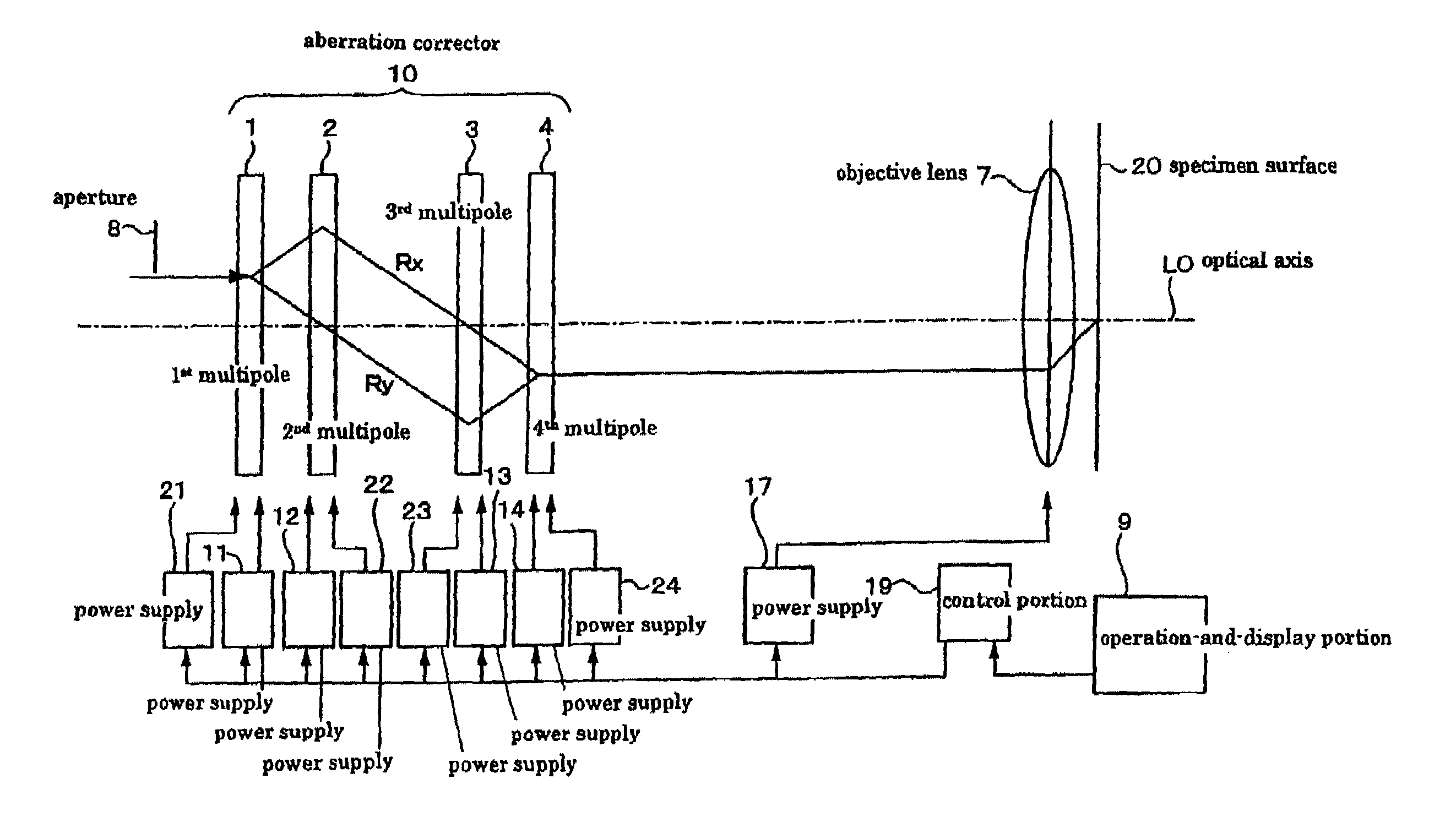
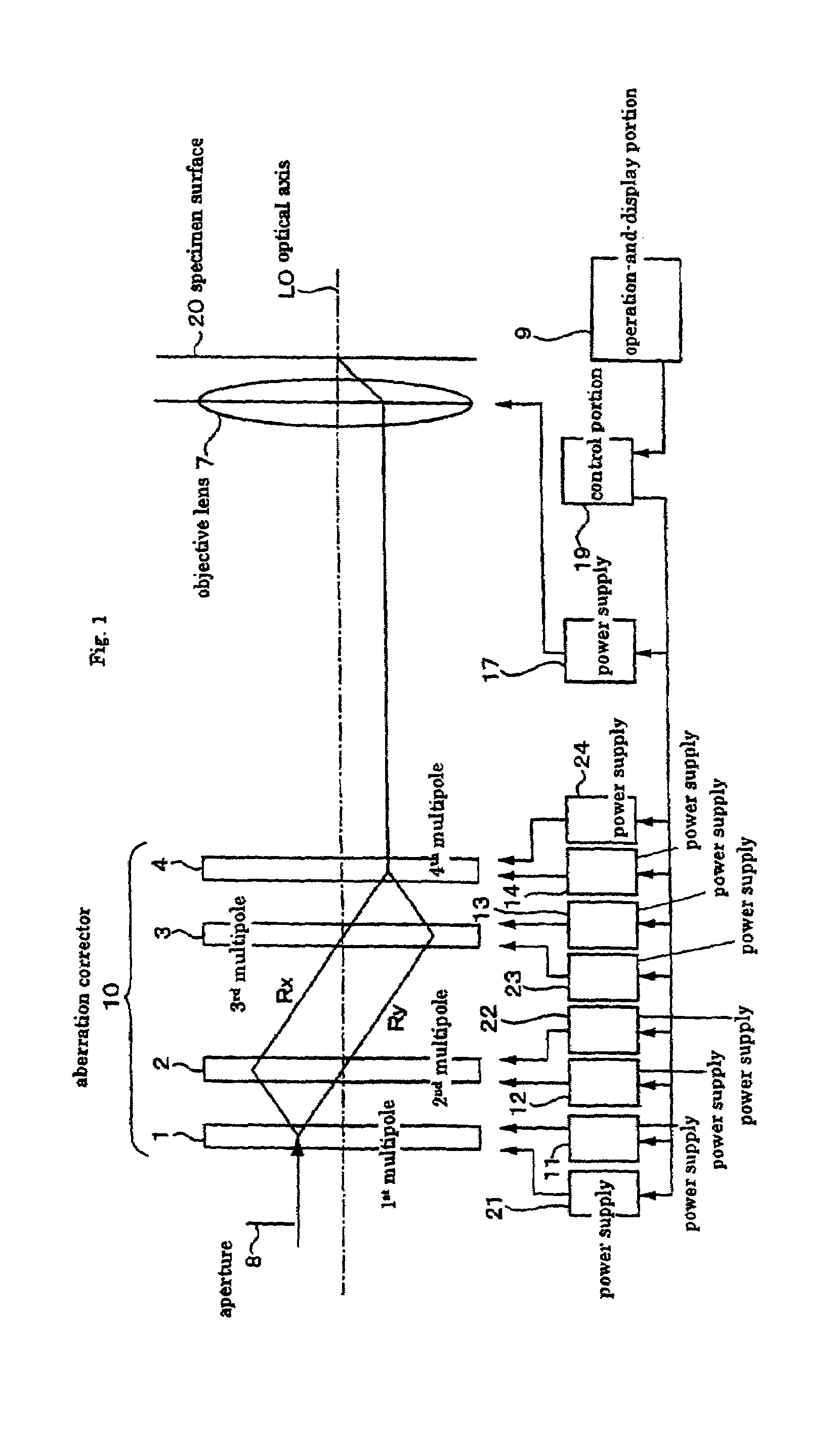
[0055]FIG. 1 shows a charged-particle optical system according to the invention. In this and following embodiments, charged-particle optical systems are similar in structure unless otherwise specifically stated.

[0056]The charged-particle optical system according to the first embodiment focuses a beam of charged particles as a probe onto a specimen. The optical system has an aperture baffle 8, four stages of multipole elements 1, 2, 3, and 4, and an objective lens 7 for focusing the beam onto a specimen surface 20. These components 8, 1–4, and 7 are arranged along the optical axis LO.

[0057]In addition, this charged-particle optical system has power supplies 11, 21 for exciting the multipole element 1, power supplies 12, 22 for exciting the multipole element 2, power supplies 13, 23 for exciting the multipole element 3, power supplies 14, 24 for exciting the multipole element 4, a power supply 17 for exciting the objective lens 7, an operation-and-display portion 9 for providing a use...

third embodiment

[0160]the invention is next described by referring to Tables 3–6.

[0161]In the correction of the fifth-order aperture aberrations, a dodecapole element in normal array in terms of electric potentials is used as a dodecapole element. Similar advantages can be obtained if a dodecapole element in skew array is used.

[0162]In this case, magnetic potentials corresponding to V1, V2, V3, and V4 are applied to the first, second, third, and fourth stages, respectively, of multipole elements such that they act as normal dodecapole fields. Electric potentials V5, V6, and V7 are applied to the first, second, and fourth stages, respectively, of multipole elements, such that they act as skew dodecapole fields. The fifth-order aperture aberrations can be corrected by the method identical with the above-described method of correcting the fifth-order aperture aberrations.

fourth embodiment

[0163]the invention is next described. In the above embodiments, it has been assumed that normal hexapole and skew hexapole components coexist simultaneously. In actual instrument, however, the hexapole components may contain no skew hexapole components. Accordingly, if there are no skew hexapole components, skew octopole fields are unnecessary to correct spherical aberration (third-order aperture aberrations). No skew decapole fields are necessary to correct the fourth-order aperture aberrations. No skew dodecapole fields are necessary to correct the fifth-order aperture aberrations. For example, where corrective voltages are computationally found from aberration coefficients, amounts of aberrations or amount of image blur, for example, if it is already obvious that there are no skew multipole components, no problems will occur provided the equations for finding the electric potentials of the skew multipole fields are removed from the simultaneous equations. Rather, this simplifies...


PUM


Abstract

On a charged-particle optical system for achieving optimum aberration correction and obtaining a minimum probe diameter, the optical system focuses a beam of charged particles onto a surface of a specimen, and has four stages of multipole elements arranged along the optical axis of the beam, power supplies capable of supplying five or more independent octopole electric or magnetic potentials, and a control portion for correcting third-order aperture aberrations by adjusting the five or more independent octopole electric or magnetic potentials independently. The power supplies apply normal octopole electric or magnetic potentials to at least three of the four stages of multipole elements independently and apply skew octopole electric or magnetic potentials to at least two of the multipole elements independently.

Description

BACKGROUND OF THE INVENTION[0001]1. Field of the Invention[0002]The present invention relates to a charged-particle optical system for use in an electron beam instrument (such as a scanning electron microscope) or a charged-particle beam instrument or device (such as an ion beam apparatus typified by an ion microprobe) to focus a beam of charged particles onto a specimen.[0003]2. Description of Related Art[0004]In a charged-particle optical system such as a scanning electron microscope or transmission electron microscope, an aberration corrector is incorporated in the charged-particle optics to enable high-resolution imaging or increase the probe current density. A system for correcting chromatic aberration by means of a combination of electrostatic quadrupole elements and magnetic quadrupole elements and for correcting spherical aberration by means of four stages of octopole elements has been proposed as such an aberration corrector. The principle is introduced in detail in H. Rose...

Claims


Application Information

Patent Timeline
Patent Type & Authority Patents(United States)
IPC IPC(8): H01J3/14H01J37/153H01J37/28
CPCH01J37/28H01J37/153
Inventor MATSUYA, MIYUKI
Owner JEOL LTD
Learn More