Dual and hybrid EGR systems for use with turbocharged engine
a hybrid and turbocharged technology, applied in the direction of machines/engines, mechanical equipment, non-fuel substance addition to fuel, etc., can solve the problems of inability to meet future emission requirements, difficult than ever to match the operation of the turbocharger to provide optimum engine performance, and inability to meet current egr technology. to meet such requirements
- Summary
- Abstract
- Description
- Claims
- Application Information
AI Technical Summary
Benefits of technology
Problems solved by technology
Method used
Image
Examples
first embodiment
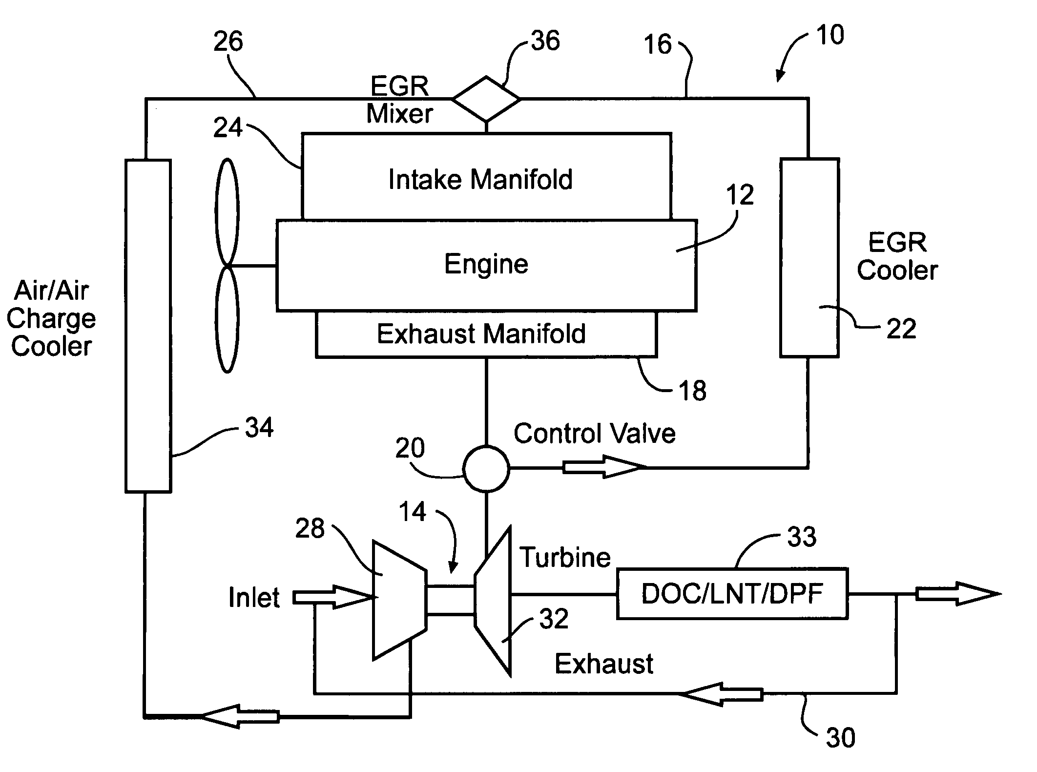
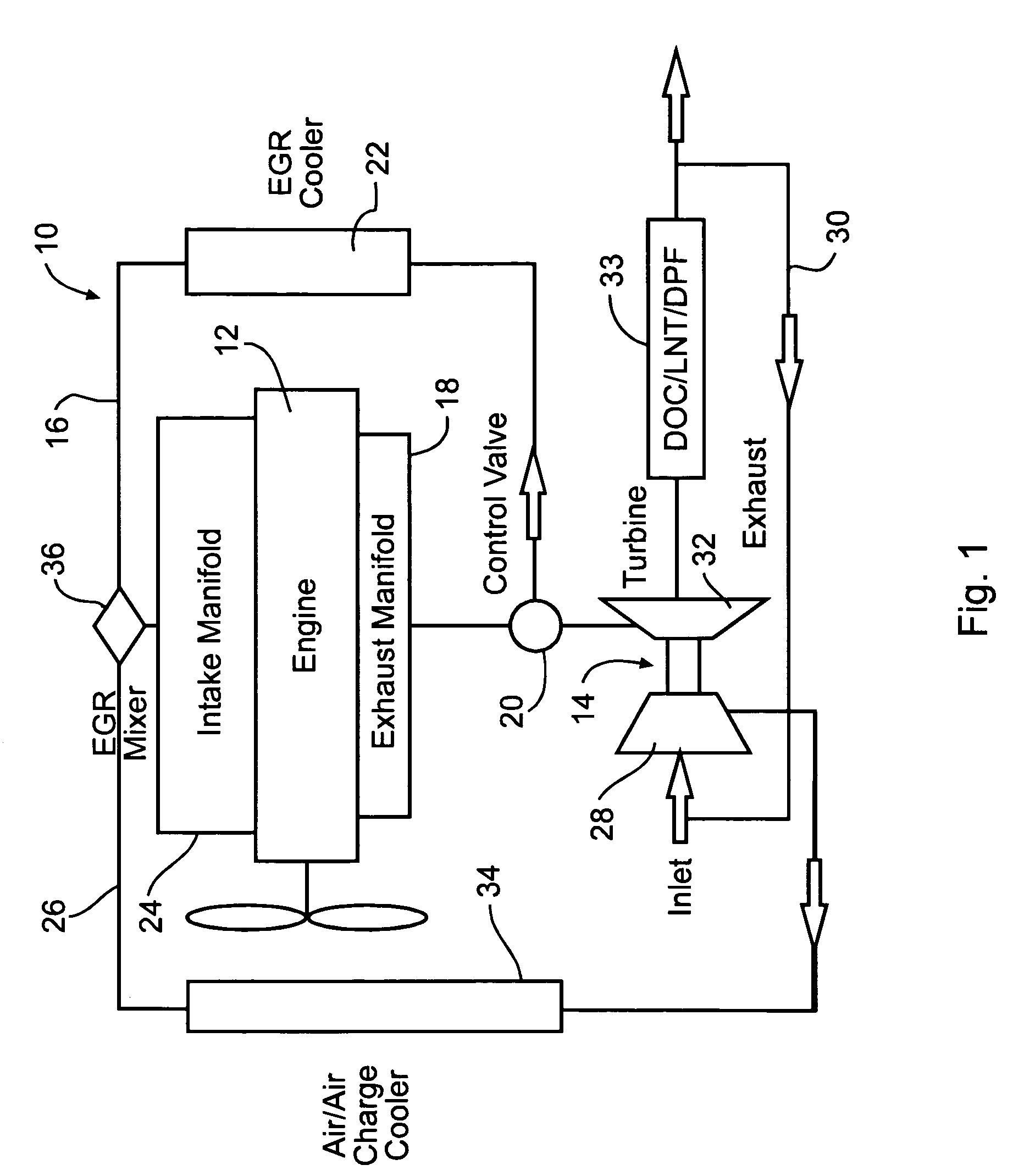
[0042]FIG. 1 illustrates a first embodiment dual EGR system 10 of this invention comprising engine 12 and turbocharger 14 connected thereto. In the example illustrated, the engine 12 is of an inline piston configuration, however EGR system 10 will work with any engine configuration. As used herein, the term “dual” is understood to refer to the fact that two EGR streams are being provided to the engine. First EGR stream 16 is provided from engine exhaust manifold 18 and is controlled via control or EGR valve 20. Cooler 22 is used to cool the first EGR stream before introduced into engine intake manifold 24. Exhaust gas from a second EGR stream is mixed with intake air and pressurized by turbocharger compressor 28. The exhaust gas for the second EGR stream is provided to an inlet end of the compressor via exhaust bypass stream 30 exiting the turbocharger turbine 32. The exhaust bypass is taken downstream of exhaust after-treatment 33, and air-to-air charge cooler 34 is used to cool pr...
second embodiment
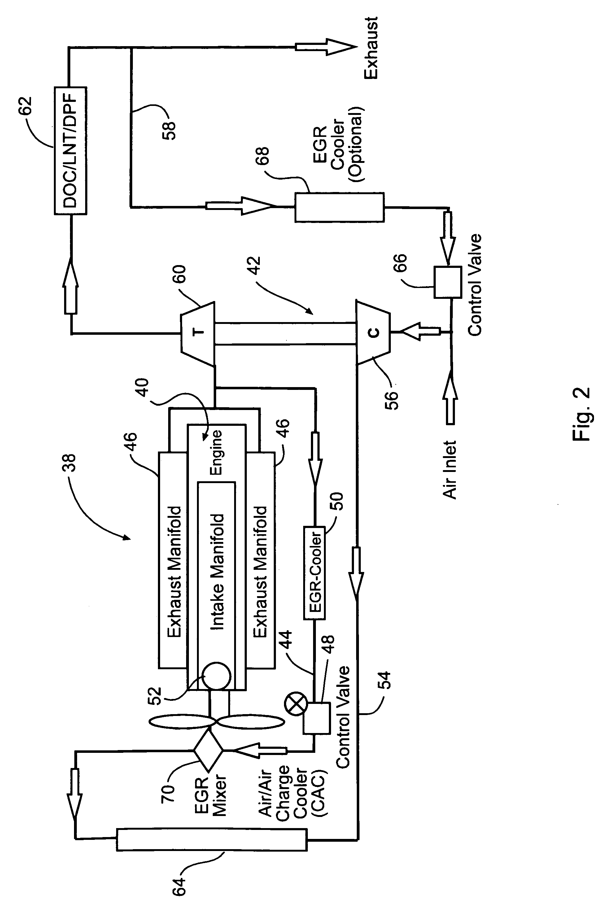
[0044]FIG. 2 illustrates a second embodiment dual EGR system 38 of this invention comprising engine 40 and turbocharger 42 connected thereto. In the example illustrated, engine 40 is of a V-8 piston configuration, however EGR system 38 will work with any engine configuration. First EGR stream / LP 44 is provided from engine exhaust manifolds 46 and is controlled via first control or EGR valve 48. Cooler 50 is used to cool the first EGR stream before introduced into engine intake manifold 52. Second EGR stream / HPL 54 is provided with pressurized intake air provided by turbocharger compressor 56. The exhaust gas for the second EGR stream is provided to an inlet end of the compressor via exhaust bypass stream 58 exiting turbocharger turbine 60. The exhaust bypass is taken downstream of exhaust after-treatment 62, and air-to-air charge cooler 64 is used to cool the pressurized intake air and second EGR stream before introduction into the intake manifold. Second control or EGR valve 66 can...
third embodiment
[0046]FIG. 3 illustrates a third embodiment dual EGR system 72 that is in many respects similar to that described above and illustrated in FIG. 2, except that the turbocharger 74 includes a compressor section 76 comprising a double sided or two-stage compressor. First compressor 78 is a low pressure compressor that receives a mix of intake air and EGR from exhaust bypass 82 and pressurizes the same before routing to second compressor 80 that is a high pressure compressor and that operates to provide a final desired boosting pressure for introduction of the mixed intake air and EGR into the engine. Charge air cooler 84 may optionally be used between the first and second compressor stages. Like the embodiment illustrated in FIG. 2, first / LP 86 and second / HPL EGR streams 88 are operated to provide desired cooled EGR for mid / full load operation, and uncooled EGR for idle / low load operation.
[0047]FIG. 4 illustrates a fourth embodiment dual EGR system 90 that is in many respects similar t...
PUM
 Abstract
Description
Claims
Application Information
 - R&D
- Intellectual Property
- Life Sciences
- Materials
- Tech Scout
- Unparalleled Data Quality
- Higher Quality Content
- 60% Fewer Hallucinations
Browse by: Latest US Patents, China's latest patents, Technical Efficacy Thesaurus, Application Domain, Technology Topic, Popular Technical Reports.
© 2025 PatSnap. All rights reserved.Legal|Privacy policy|Modern Slavery Act Transparency Statement|Sitemap|About US| Contact US: help@patsnap.com


