
Electric heating apparatus with housing

a heating apparatus and housing technology, applied in the direction of resistors, heater elements, air heaters, etc., can solve the problems of inability to use electric heating apparatuses, and inability to meet the contact pressure forces of resilients, etc., to achieve the effect of improving the structur

Active Publication Date: 2006-03-14
CATEM
View PDF6 Cites 23 Cited by
  • Summary
  • Abstract
  • Description
  • Claims
  • Application Information

AI Technical Summary

Benefits of technology

"The present invention provides an improved electric heating apparatus with a simplified production process. The invention includes a contact sheet with a layer of lacquer for protection against corrosion, which is applied during production. The lacquer layer is pressed out to seal the connection between the contact sheet and the PTC heating element. The invention also includes a pre-fabricated constructional unit with a radiator element, a contact sheet, and the PTC heating element secured through the lacquer, which simplifies production and reduces costs. The invention further includes a housing made of plastics, which allows for efficient heat transfer and is lightweight and cost-effective. The invention also includes a grid structure of longitudinal and transverse struts to prevent bending or deflection of the housing. Overall, the invention provides an improved electric heating apparatus with improved protection against corrosion, simplified production process, and efficient heat transfer."

Problems solved by technology

That is why such electric heating apparatuses are not suited for use in the case of very small installation heights.
When electric heating apparatuses with an exterior holding frame or exterior clamping action are assembled, troublesome measures are needed for counteracting the contact pressure forces of the resilient means / frame that are objectionable during assembly.
Due to these drawbacks heating apparatuses with a conventional holding frame for modern air conditioners, especially for installation in automotive vehicles, are less and less suited.
Furthermore, conventional constructions with a holding frame, particularly of metal, have a considerable weight.
A further drawback of metal holder frames is their conductive surface.
A further drawback of conventional electric heating apparatuses is the risk of corrosion of contact sheets supplying the heating elements with current.
The possibility that contact sheets get into contact with moisture exists both during the manufacturing process and during operation.
Corrosion between a PTC heating element and a contact sheet made e.g. from aluminum may effect a loss in power of up to about 30%.

Method used


Image

  • Electric heating apparatus with housing
  • Electric heating apparatus with housing
  • Electric heating apparatus with housing

Examples


Embodiment Construction

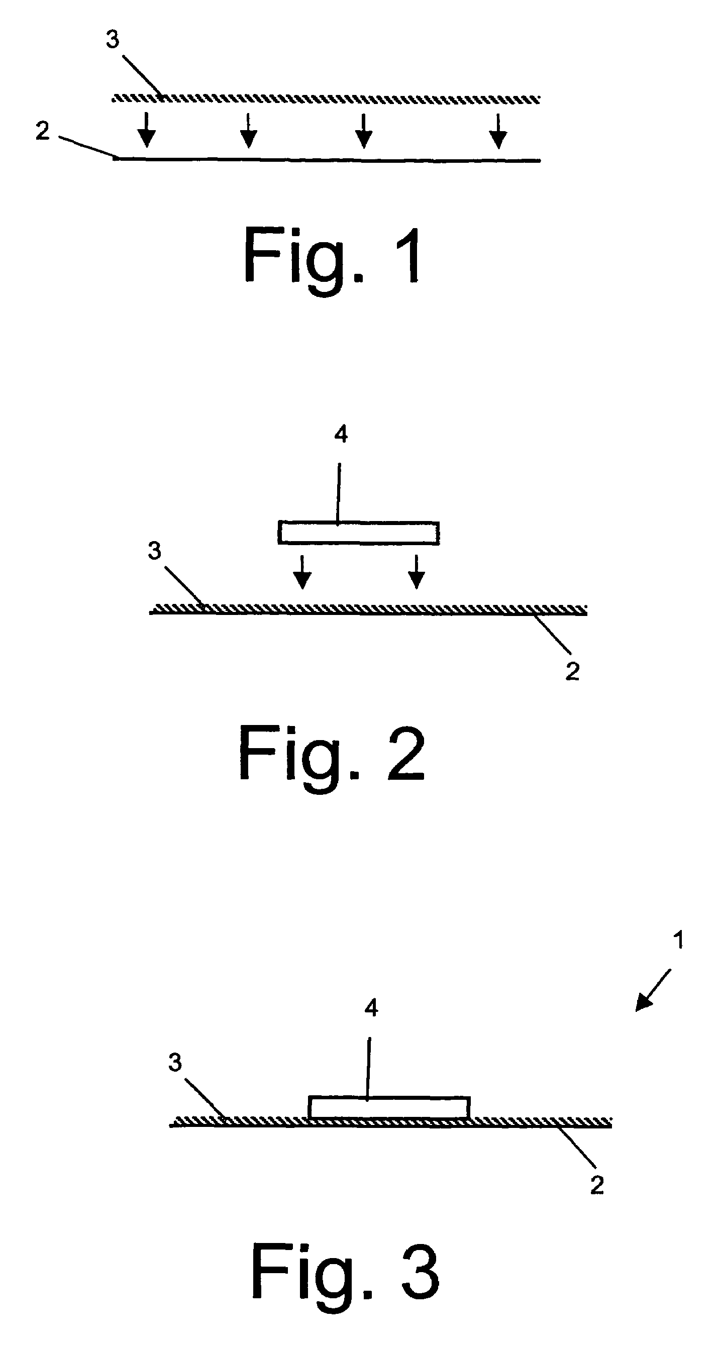
[0070]While in conventional electric heating apparatuses, the PTC heating elements are positioned via positioning means, such as a position frame, between contact sheets, electric heating apparatuses according to the invention are produced such that at least one of the contact sheets is provided with a lacquer layer and the PTC heating elements are positioned thereon prior to assembly in the electric heating apparatus. Said manufacturing steps are shown in FIGS. 1 to 3 in an illustrative manner.

[0071]FIG. 1 is a schematic side view of a contact sheet 2 provided with a lacquer layer 3 at the side later facing the PTC heating element. Subsequently, the PTC heating element 4 is mounted on said lacquer layer 3 (FIG. 2). The contact sheet 2 with the lacquer layer 3 and the PTC heating element 4 arranged thereon form a prefabricated constructional unit 1, which is schematically shown in FIG. 3.

[0072]The firmness of the fixation of PTC heating elements 4 via the lacquer 3 on the contact sh...


PUM


Abstract

Electric heating apparatus and manufacturing method for an electric heating apparatus, wherein prefabricated constructional units are used. The prefabricated constructional units consist of PTC heating elements fastened to contact sheets by means of a lacquer. This simplifies production and enhances protection against corrosion.

Description

BACKGROUND OF THE INVENTION[0001]1. Field of the Invention[0002]The present invention relates to an electric heating apparatus, particularly as an additional or auxialliary heater for automotive vehicles, a constructional unit for such a heating apparatus, and a corresponding manufacturing method.[0003]2. Description of the Related Art[0004]For use in automotive vehicles, particularly automotive vehicles with new, consumption-optimized engines, in which a reduced amount of heat energy is observed, electric additional heaters are used for heating passenger compartment and engine. Such electric heating apparatuses are however also suited for other purposes, e.g. in the field of building installations, particularly room air conditioning, in industrial plants, or the like.[0005]Preferably, PTC heating elements with radiator elements in heat-conducting communication are used for an electric additional heater for an automotive vehicle. The heat generated by the PTC heating elements is dis...

Claims


Application Information

Patent Timeline
Patent Type & Authority Patents(United States)
IPC IPC(8): H05B3/06H05B3/10H05B3/20H05B3/12H05B3/14H05B3/50
CPCF24H3/0429F24H9/1872H05B3/50H05B3/14H05B2203/02B25C5/0221B25C5/11
Inventor BOHLENDER, FRANZWALZ, KURT
Owner CATEM
Learn More