
Electronically controlled hydraulic brake system

a hydraulic brake and electric control technology, applied in the direction of braking systems, positive displacement liquid engines, instruments, etc., can solve the problems of inability to linearly compensate the non-linear characteristic of the brake hydraulic pressure pwc, and degradation of the brake respons

Inactive Publication Date: 2006-03-07
NISSAN MOTOR CO LTD
View PDF8 Cites 10 Cited by
  • Summary
  • Abstract
  • Description
  • Claims
  • Application Information

AI Technical Summary

Benefits of technology

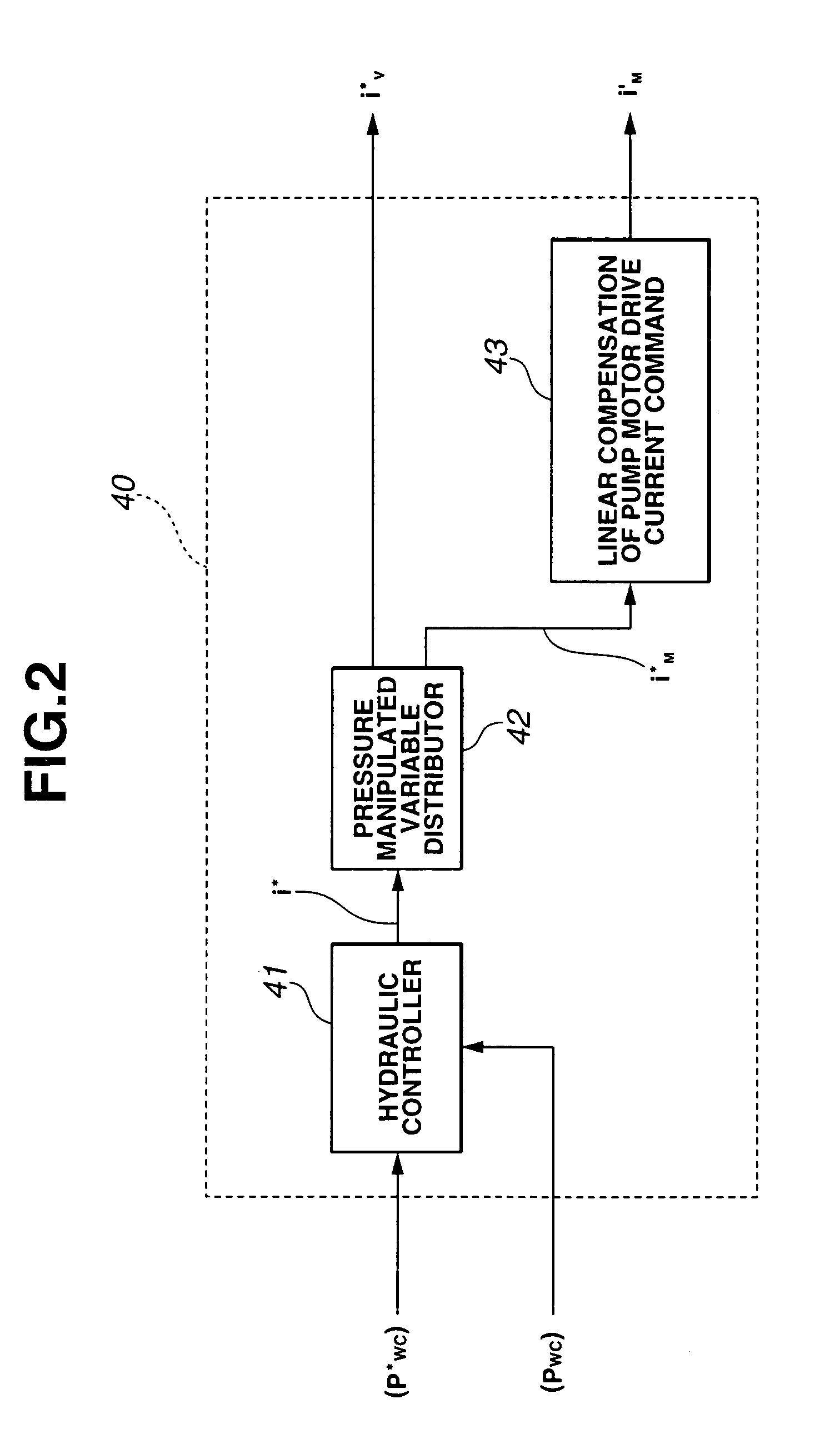
[0006]It is therefore an object of the present invention to provide an improved electronically controlled hydraulic brake system which solves the problem as to the brake response so as to securely execute the linear compensation of the non-linear characteristic of the brake hydraulic pressure by employing a specific idea in producing the motor drive current command value for the motor of a pressure increasing pump.

Problems solved by technology

However, it is impossible to linearly compensate the non-linear characteristic of brake hydraulic pressure Pwc after brake hydraulic pressure Pwc reached the attainment brake hydraulic pressure since time change rates θ1, θ2 and θ3 of hydraulic pressure Pw are zero.
This response delay causes a problem relating to the degradation of the brake response.

Method used


Image

  • Electronically controlled hydraulic brake system
  • Electronically controlled hydraulic brake system
  • Electronically controlled hydraulic brake system

Examples


Embodiment Construction

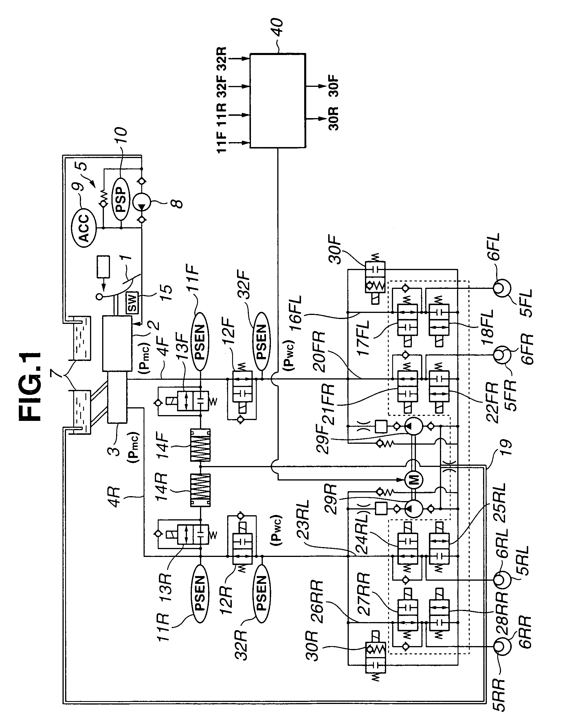
[0023]Referring to the drawings, there is discussed an embodiment of an electronically controlled hydraulic brake system according to the present invention. FIG. 1 shows a system view of the electronically controlled hydraulic brake system for a vehicle according to the embodiment of the present invention. This electronically controlled hydraulic brake control system is applicable to a coordinated regenerative brake control system wherein a brake hydraulic pressure and a regenerative brake employing an alternating-current synchronous motor (not shown) are coordinately controlled. Further, the electronically controlled hydraulic brake control system comprises a front-wheel brake hydraulic pressure line and a rear-wheel brake hydraulic pressure line, so as to be coordinately controlled with the regenerative-brake motor provided for front wheels or rear wheels and to be adapted to a front and rear split line arrangement. Accordingly, the electronically controlled hydraulic brake system...


PUM


Abstract

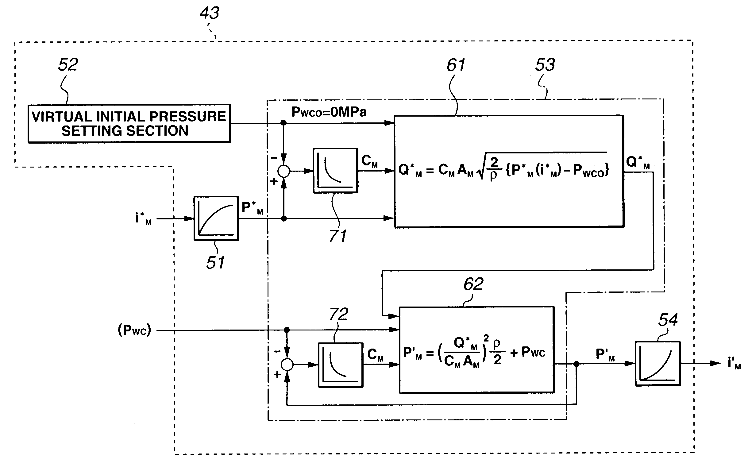
An electronically controlled hydraulic brake system is configured to obtain an attainment brake hydraulic pressure which can be achieved when a motor drive current command value is applied to a pressure increasing pump motor, to set a virtual initial pressure of the brake hydraulic pressure, to obtain a linear compensation executed attainment brake hydraulic pressure by linearly compensating the attainment brake hydraulic pressure using the actual brake hydraulic pressure, to calculate an ideal flow rate of the pressure increasing pump from a hydrodynamic flow rate equation, to obtain the linear compensation executed attainment brake hydraulic pressure by executing an inverse calculation of the flow rate equation from the ideal flow rate and the actual brake hydraulic pressure, and to obtain a linear compensation executed motor drive current command value by executing an inverse calculation of the calculation for obtaining the linear compensation executed attainment brake hydraulic pressure.

Description

BACKGROUND OF THE INVENTION[0001]The present invention relates to an electronically controlled hydraulic brake system which increases a brake hydraulic pressure by supplying brake fluid into a brake hydraulic pressure line by means of an electronically controlled pressure increasing pump, and more particularly to a method of controlling a drive current command value of a motor for the pressure increasing pump so as to linearly compensate a non-linear characteristic of the brake hydraulic pressure.[0002]Japanese Published Patent Application No. 2001-301592 discloses an electronic control system for a pump drive motor in an electronically controlled hydraulic brake system shown in FIG. 10. This electronic control system is arranged to obtain a demand motor output (feedforward controlled variable) Ws by multiplying a rate dPmc / dt of change (changing speed) of a master cylinder hydraulic pressure (brake hydraulic pressure command value) Pmc and a coefficient C1 according to the rate of ...

Claims


Application Information

Patent Timeline
Patent Type & Authority Patents(United States)
IPC IPC(8): B60T7/12B60T8/00B60L7/26B60T8/40F04B49/06
CPCB60L7/26B60T8/4054B60T8/4081F04B49/065F04B2205/09F04B2203/0201F04B2205/05B60T2220/04
Inventor ZHANG, JICHENGNAKAMURA, HIDEO
Owner NISSAN MOTOR CO LTD
Learn More