
Multichannel electrode and methods of using same

Inactive Publication Date: 2006-03-07
LONDON HEALTH SCI CENT RES +1
View PDF13 Cites 285 Cited by
  • Summary
  • Abstract
  • Description
  • Claims
  • Application Information

AI Technical Summary

Benefits of technology

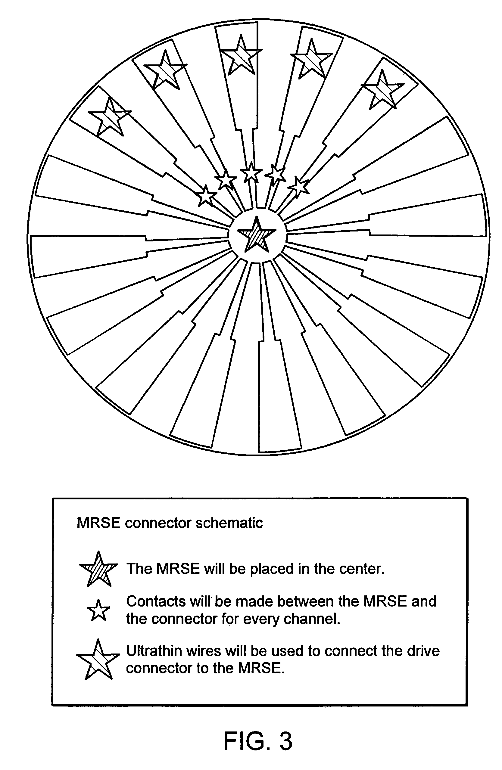
[0010]Preferably, the non-planar backbone comprises an electrically conductive layer. In one aspect, the non-planar backbone is bonded to an electrically conductive material and electrode channels are micromachined or microlithographically etched into the electrically conductive material. Preferably, the channels are micromachined by laser micromachining or other methods. In another aspect, the non-planar backbone comprising electrode channels is contained partially within a probe housing with at least its tip exposed. The probe housing can be designed to facilitate handling by a user and for connection to a drive system used to activate and control the movement of the MC electrode. Preferably, the MC electrode can be advanced and retracted and / or rotated to enhance its ability to localize a target. This can be achieved by providing an interfacing connector in communication with a microdrive device.
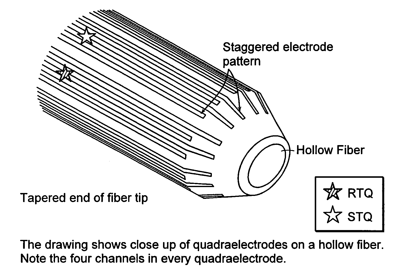
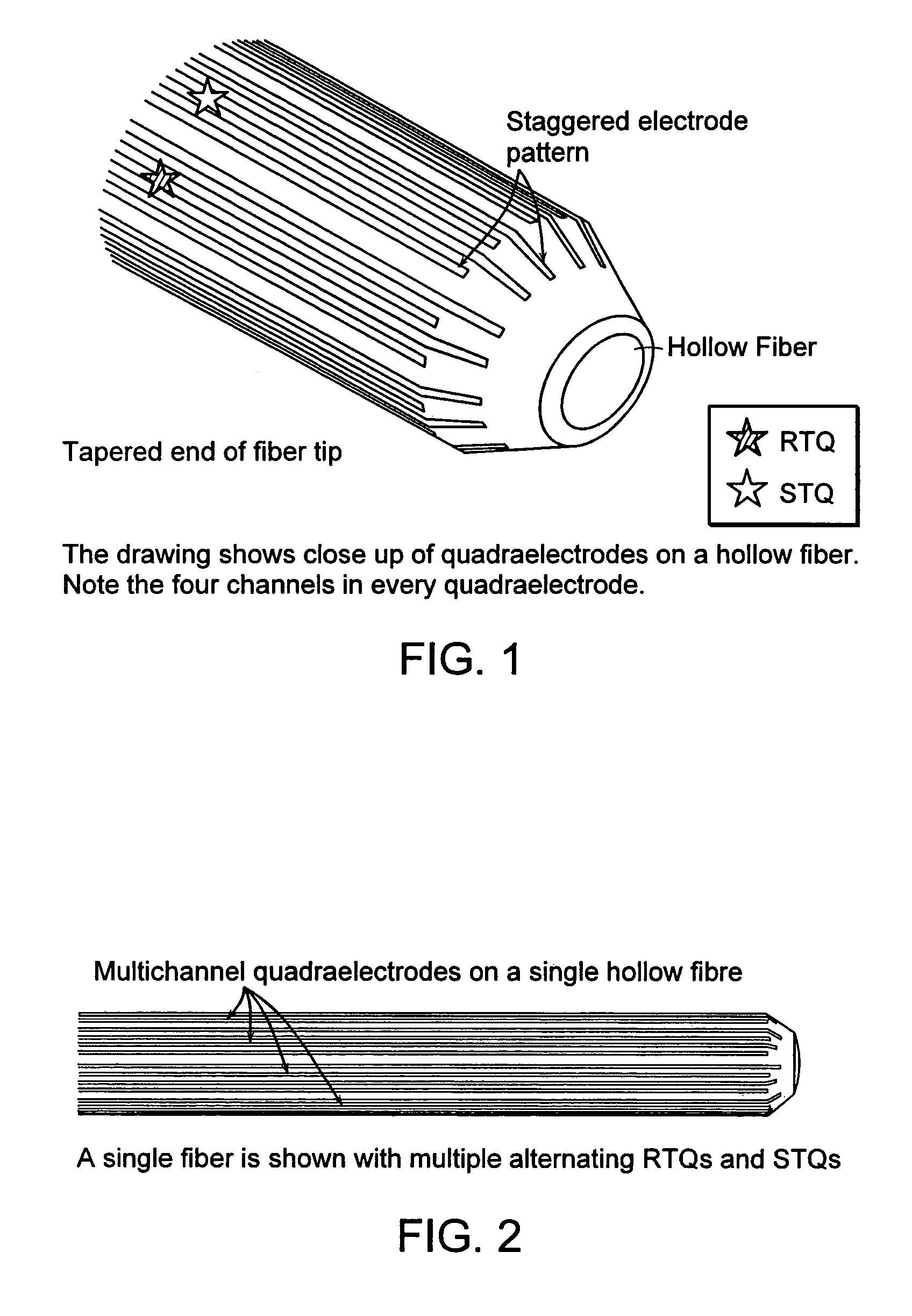
[0028]In one aspect, the backbone is hollow to facilitate the transmission of light (e.g., the backbone itself can be a hollow optical fiber to provide annular ring light). In another aspect, a light path is provided in the form of a fiber which is itself placed within the hollow backbone. In still another aspect, bundles of optical fibers are provided within the lumen of the hollow backbone. In a further aspect, a backbone is provided which comprises a groove or channel along its side into which a light guide or optical fiber can be fitted. The light guide or fiber can be coupled to a camera to facilitate the imaging process.

Problems solved by technology

Because of the large surface area these electrodes occupy, they generally are suited only for recording and stimulating neurons at the surface of the brain and are not for use in deep brain procedures.

Method used


Image

  • Multichannel electrode and methods of using same
  • Multichannel electrode and methods of using same
  • Multichannel electrode and methods of using same

Examples


example 1

Design and Testing of Four Channel Prototype Electrodes

[0225]A gold plated copper-backed flex circuit board was first glued onto a gold-coated metal rod backbone. Three of the four channels were precisely machined using a depth control machining technique on the circuit board leaving the underneath plastic insulating material intact. The board was then mounted on to a 0.5 mm diameter gold-coated metal rod backbone with a fourth channel machined on it. Electrode connector pads were attached to wires for data measurements (see, FIG. 4). The machined width of the individual channels of the electrode was 15±2 μm. The electrode was then partially covered with an insulating plastic material leaving 4±1 μm of the tip uninsulated. The spacing between the four channels at the tip was 20±5 μm (see, FIG. 5).

[0226]To determine the amount of current deliverable through fine wire cross-sections of varying diameters measurements were initially performed on 25 μm and 37.5 μm diameter copper-gold fl...


PUM


Abstract

The invention provides a multichannel electrode (“MC electrode”) which can perform multiple functions such as recording, stimulating and lesioning simultaneously or sequentially upon a single insertion into a target site. In one aspect, the MC electrode further provides imaging and drug delivery capabilities. The invention also provides interface connectors for connecting the MC electrode to external units such as data acquisition and / or stimulation systems. Although the MC electrode and associated connectors and system(s) provide an optimal way to perform deep brain surgical procedures, the MC electrode and associated connectors and system(s) are useful generally in any technique which relies on recording, activating, and / or inhibiting electrical signals produced by cells.

Description

FIELD OF THE INVENTION[0001]The invention relates to a multichannel electrode comprising a non-planar backbone for use in medical procedures, particularly neurosurgical procedures.BACKGROUND OF THE INVENTION[0002]During neurosurgical procedures, electrodes are commonly used to monitor electrical activity and stimulate and / or lesion neural tissue. Typically, electrodes are brought into the vicinity of cell membranes so that an electrical transition resistance (impedance) is created between the cells and the electrodes. Electrical stimulation of a malfunctioning neuron can be used to activate or reversibly block neural activity, while lesioning can be used to permanently disable neuronal activity. U.S. Pat. No. 1,662,446, issued to Wappler, teaches an early electrode system.[0003]The recent resurgence of procedures to stimulate and produce lesions in deep brain structures for the treatment of Parkinson's disease, tremor, and dystonia, has been due not only to a better understanding of...

Claims


Application Information

Patent Timeline
IPC IPC(8): A61N1/05A61B5/296
CPCA61N1/0551A61N1/0536
Inventor JOG, MANDARNIKUMB, SUWAS
Owner LONDON HEALTH SCI CENT RES
Learn More