Eureka AIR delivers breakthrough ideas for toughest innovation challenges, trusted by R&D personnel around the world.

Switch using a segmented ring

a segmented ring and switch technology, applied in the direction of electrical equipment, data switching networks, digital transmission, etc., can solve the problems of limited processing ability at 10 gbit rate and above, common set of problems in the hardware and software systems designed to meet the performance criteria of the next generation of switches, etc., to achieve higher switching rates and higher switching rates.

Active Publication Date: 2006-03-07
AVAGO TECH INT SALES PTE LTD
View PDF66 Cites 10 Cited by
  • Summary
  • Abstract
  • Description
  • Claims
  • Application Information

AI Technical Summary

Benefits of technology

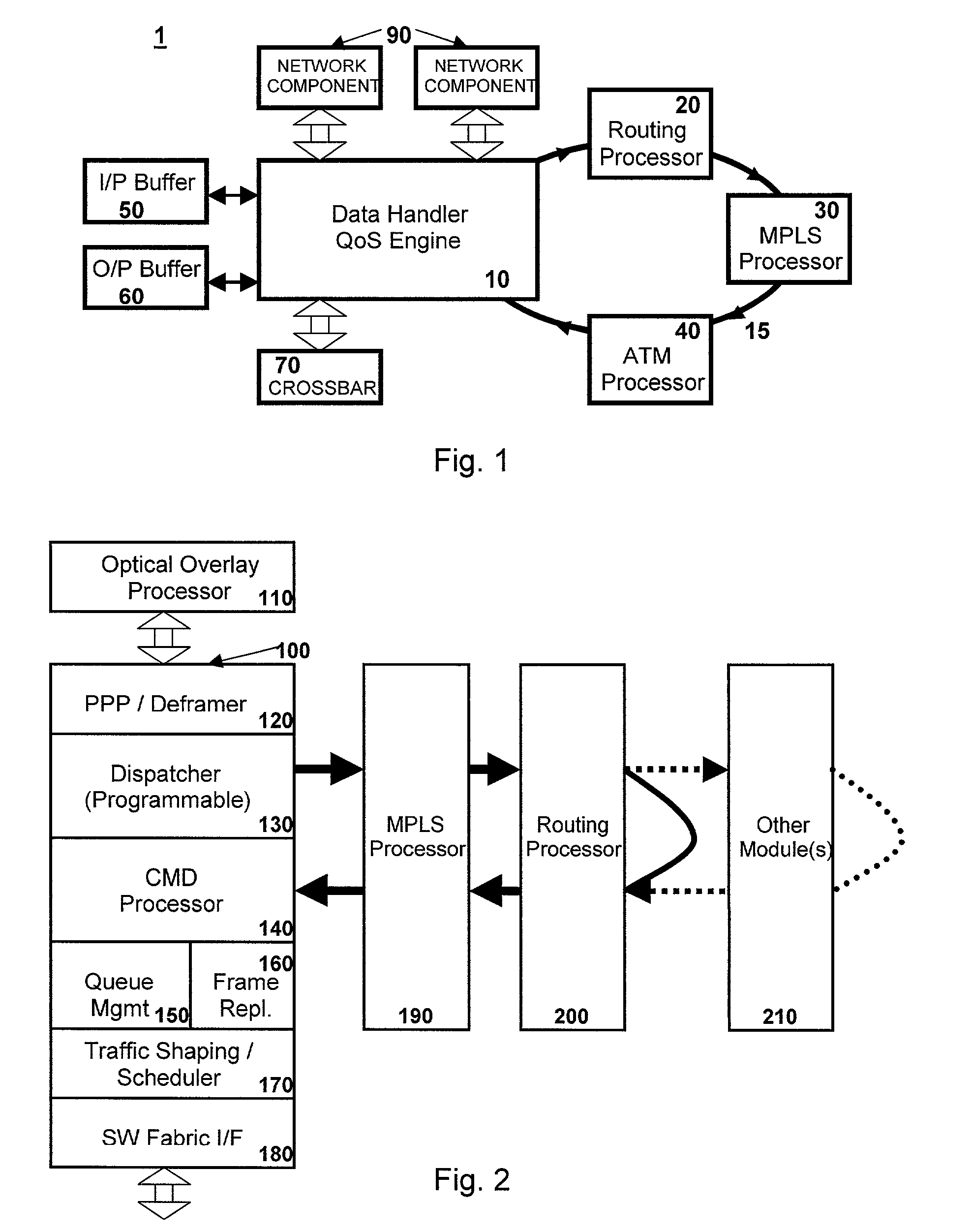
[0010]Accordingly, it is a principal object of the present invention to provide a switch that can operate at higher switching rates and adaptable to different network configurations. The present invention provides for dedicated modules, that can be swapped in or out depending on the needs of the switching environment, and an architecture that passes information to these dedicated modules and allows the modules to request more information and / or pass the information to another module. Based on the dedicated modules configured in the architecture, the switch can handle routing specific to the network requirements into which the switch is placed. Thus, the switch is fully scalable and can achieve higher switching rates because of the dedicated hardware modules.

Problems solved by technology

The hardware and software systems designed to meet the performance criteria for the next generation of switches have a common set of problems.
In the prior art, the ability to process at the 10 Gbit rate and above is limited by the software used in switching and packet processing.
The difficulty with dedicated hardware solutions is that they are, by design, directed to specific processing environments and many different network components would be necessary to meet the needs of differing network setups.

Method used


Image

  • Switch using a segmented ring
  • Switch using a segmented ring
  • Switch using a segmented ring

Examples


Embodiment Construction

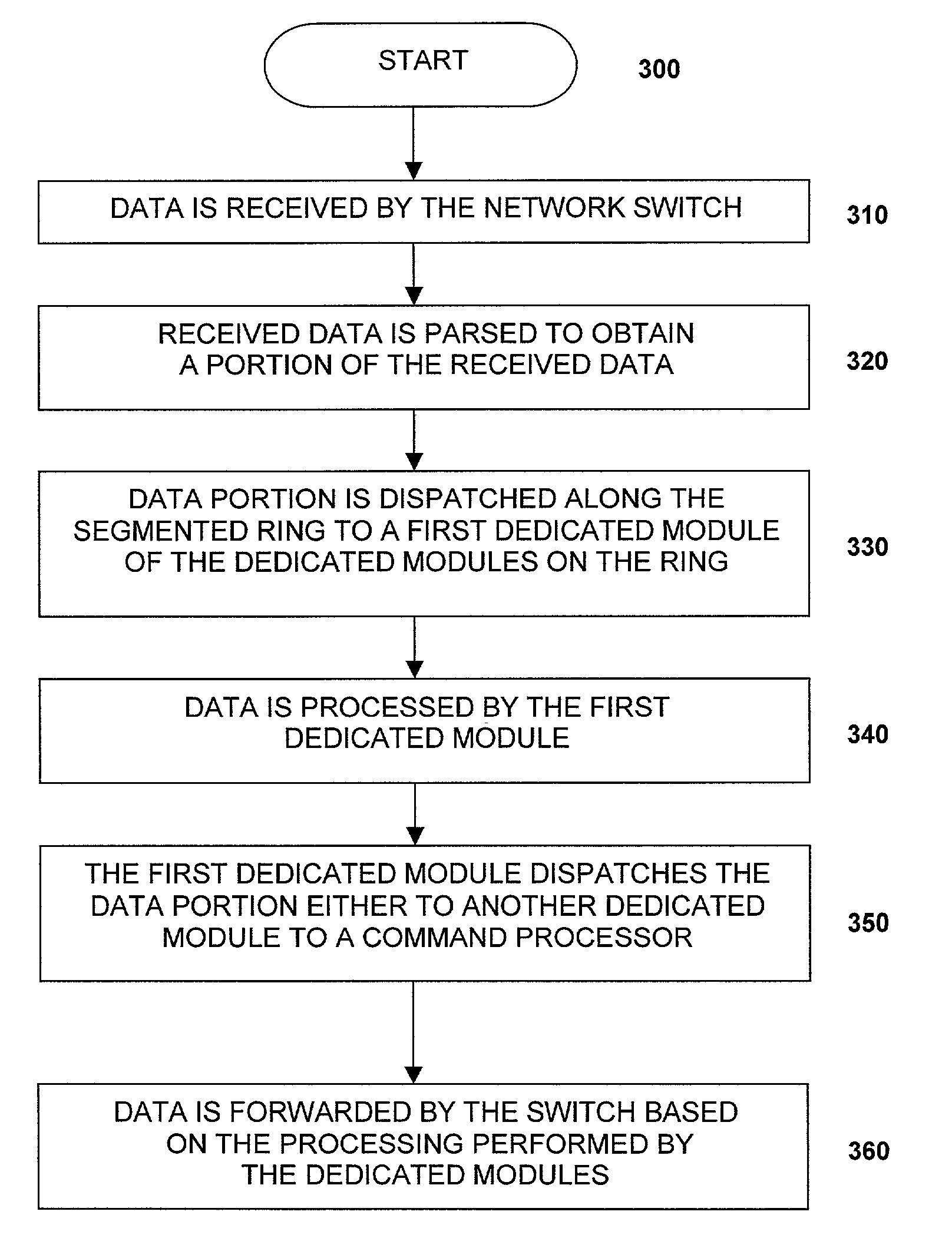
[0019]The present invention is directed to a network switch and a method for processing data by a network switch. The present invention provides of a high bandwidth architecture to ensure that data is not dropped and that data packets are managed effectively. The architecture of the present invention creates a separate channel for the datapath and forwarding / management information in each packet or cell. A ring structure is used to manage the Header / Delivery / Priority / Management information for the packets or cells while the datagram is handled by a packet processor. The architecture allows for a modular building block approach based on a programmable dispatcher and application specific and / or protocol specific processors designed for the ring.

[0020]In the context of the present application, a packet is defined as the entire transmitted bit sequence as viewed on a network medium, from the first bit of the preamble sequence to the last bit of the Frame Check Sequence (FCS) field. A fr...


PUM


Abstract

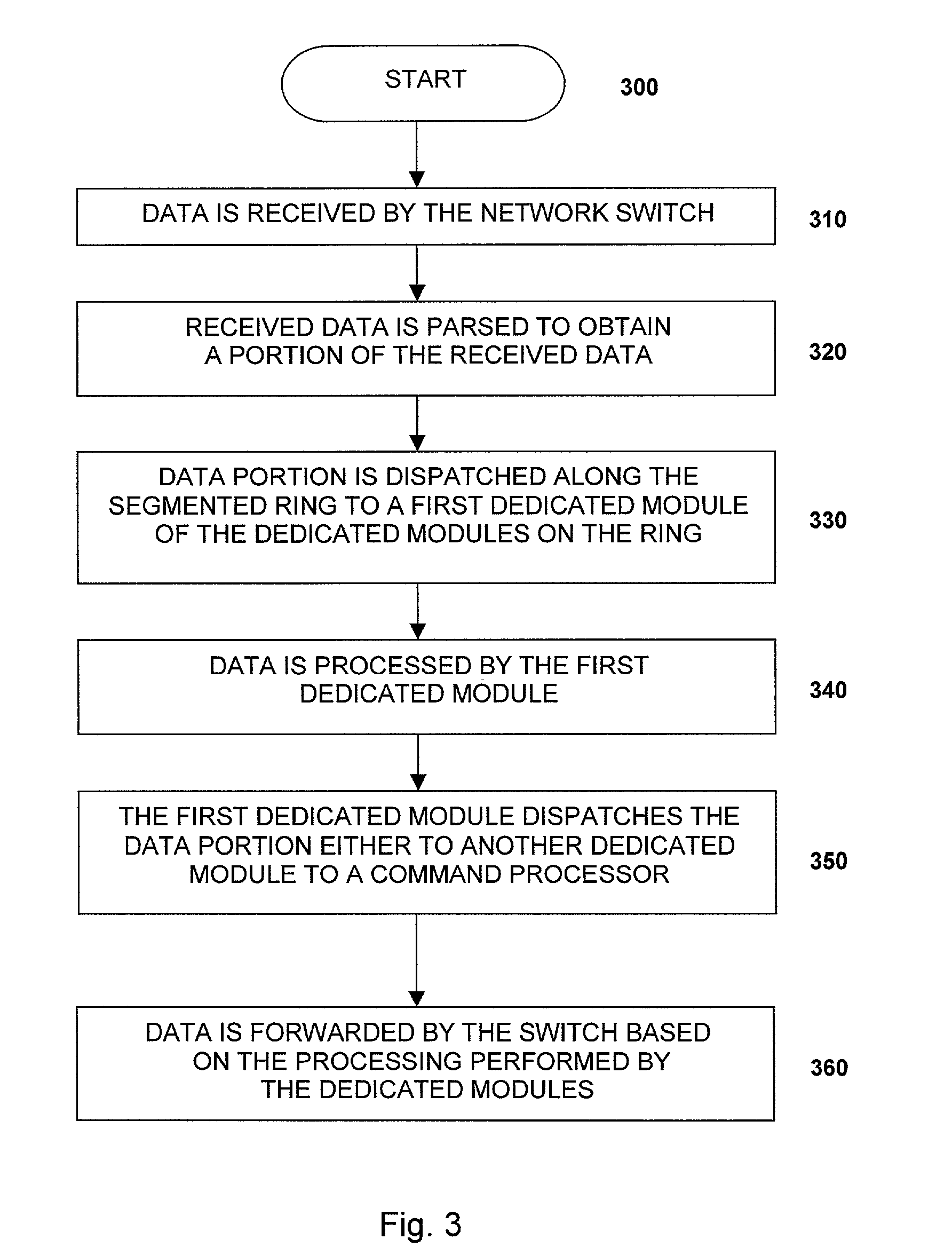
A network switch is disclosed having at least one data port interface for receiving data and at least one link interface configured to transmit the data between the network switch and other network switches. The switch contains a data processor, having a segmented ring with a plurality of dedicated modules designed to process the data connected through that ring. A programmable ring dispatcher dispatches at least a portion of the data along a segmented ring to at least one of the dedicated modules. The data processor also has a command processor for processing commands received from the dedicated modules. The programmable ring dispatcher determines the first dedicated module to receive the portion of the data and that first dedicated module thereafter determines the next destination for the data potion. Because the dedicated modules can be added to or taken out the switch architecture based on the network environment, the switch is scalable and adaptable.

Description

REFERENCE TO RELATED APPLICATIONS[0001]This application claims priority to U.S. Provisional Patent Application Ser. No. 60 / 185,271, filed on Feb. 28, 2000. The contents of this patent application is hereby incorporated by reference.BACKGROUND OF THE INVENTION[0002]1. Field of the Invention[0003]The invention relates to a method and apparatus for high performance switching in local area communications networks such as token ring, ATM, ethernet, fast ethernet, and gigabit ethernet environments, generally known as LANs. In particular, the invention relates to a high bandwidth architecture for an optical switch or packet processor and methods that provide efficient processing of cell and packetized data by the optical switch or packet processor.[0004]2. Description of the Related Art[0005]As computer performance has increased in recent years, the demands on computer networks have increased. Faster computer processors and higher memory capabilities need networks having high bandwidths to...

Claims


Application Information

Patent Timeline
Patent Type & Authority Patents(United States)
IPC IPC(8): H04L12/56
CPCH04L49/102H04L49/201H04L49/351H04L49/3018H04L49/205
Inventor CAO, JUNDAI, WILLIAMKIM, YONGBUM
Owner AVAGO TECH INT SALES PTE LTD
Why Eureka
Eureka Blog
Learn More