
Apparatus for oxygenating wastewater

a technology of oxygenating apparatus and wastewater, which is applied in water cleaning, multi-stage water/sewage treatment, separation processes, etc., can solve the problems of contaminating the water supply, affecting the oxygenation effect of wastewater, so as to achieve convenient maintenance or increase the oxygenation effect at the site, simplify the assembly, and simplify the cleaning

Inactive Publication Date: 2006-03-07
WAYNE STATE UNIV +1
View PDF477 Cites 111 Cited by
  • Summary
  • Abstract
  • Description
  • Claims
  • Application Information

AI Technical Summary

Benefits of technology

[0020]Advantageously, the distal end of the hose includes or is coupled to a delivery nozzle including one or more capillaries through which the oxygen-enriched water effluent passes. The capillaries may be dimensioned to an appropriate length and diameter for a desired flow rate, oxygen concentration, and other flow characteristics such as substantially laminar and bubble free flow. The capillaries are advantageously made of silica, and may be dimensioned to a length of about 6 cm and an internal diameter of about 150 to 450 microns. Alternatively, the capillaries may be constructed from a variety of metals, metal alloys, glasses, plastics / polymers, ceramics or other suitable materials. For an oxygen-enriched water flow rate of about 1.5 gal / min, at about 300 p.s.i., a delivery nozzle including approximately 450 such capillaries is particularly advantageous. The capillaries tend to stabilize the gas-enriched water during its delivery into host liquids at ambient pressure. As a result, nucleation and bubble formation in the effluent, during ejection from the capillary and mixing with the host liquid, is minimal or absent despite potentially high gas partial pressures of the oxygen dissolved in the effluent. An extremely high oxygen transfer efficiency, approaching or even equaling 100 percent, is thereby achievable with this approach for oxygenating host liquids such as wastewater.
[0023]An alternate embodiment of the plate-based delivery nozzle system may employ one or more conical plates to create an annular array of fluid pathways. The conical plates have a plurality of channels, which extend linearly along an inner or outer surface between a small and broad end of the conical plates. The conical plates stack in series such that the outer surface of one conical plate is disposed within the inner surface of another conical plate, thereby creating an annular array of fluid pathways between adjacent conical plates. The conical plates are then truncated at one end to provide a common entry position for the oxygen-enriched water and are configured such that the opposite end forms a desired exit surface (i.e., conical, concave, flat, etc.). The conical plate design may advantageously simplify assembly, as the oxygen-enriched water flow forces the conical plates together during use, and may simplify cleaning, as reversed water flow may be used to separate and clean the conical plates.
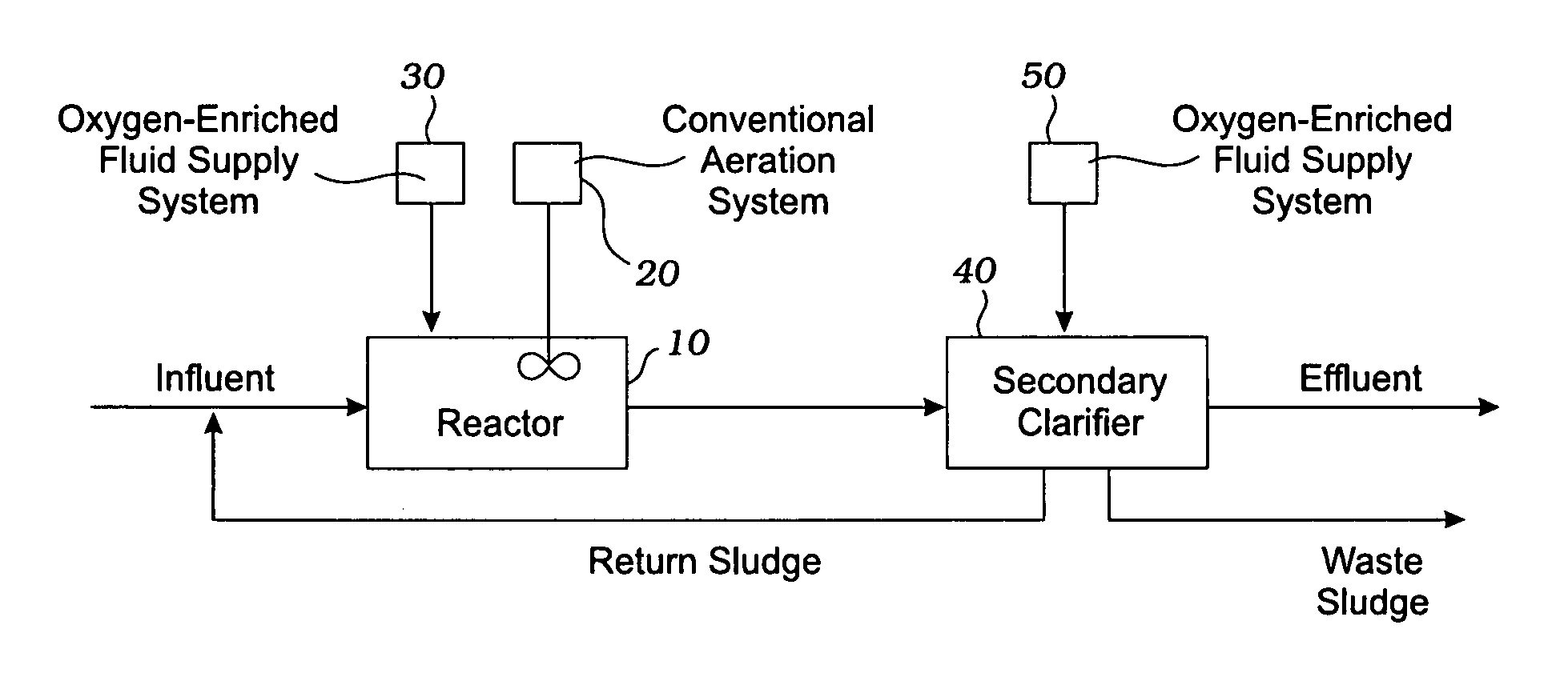
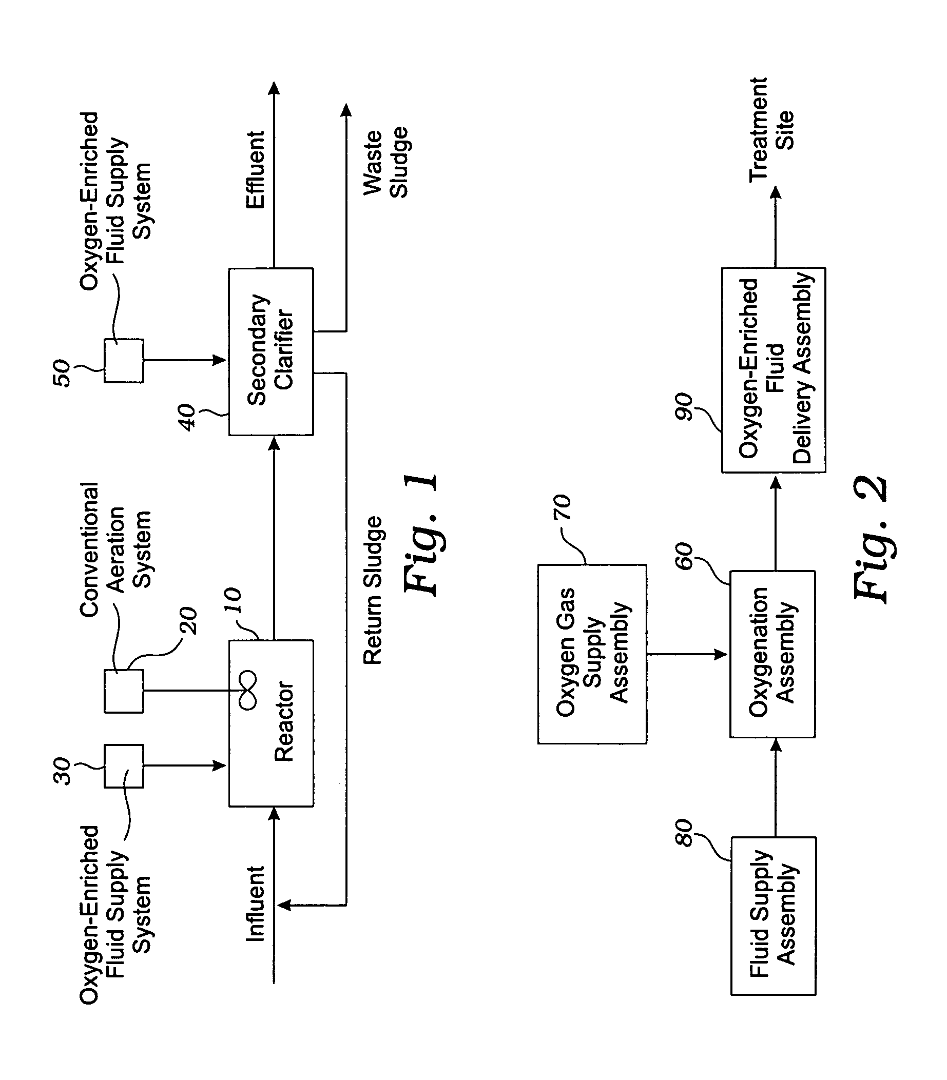
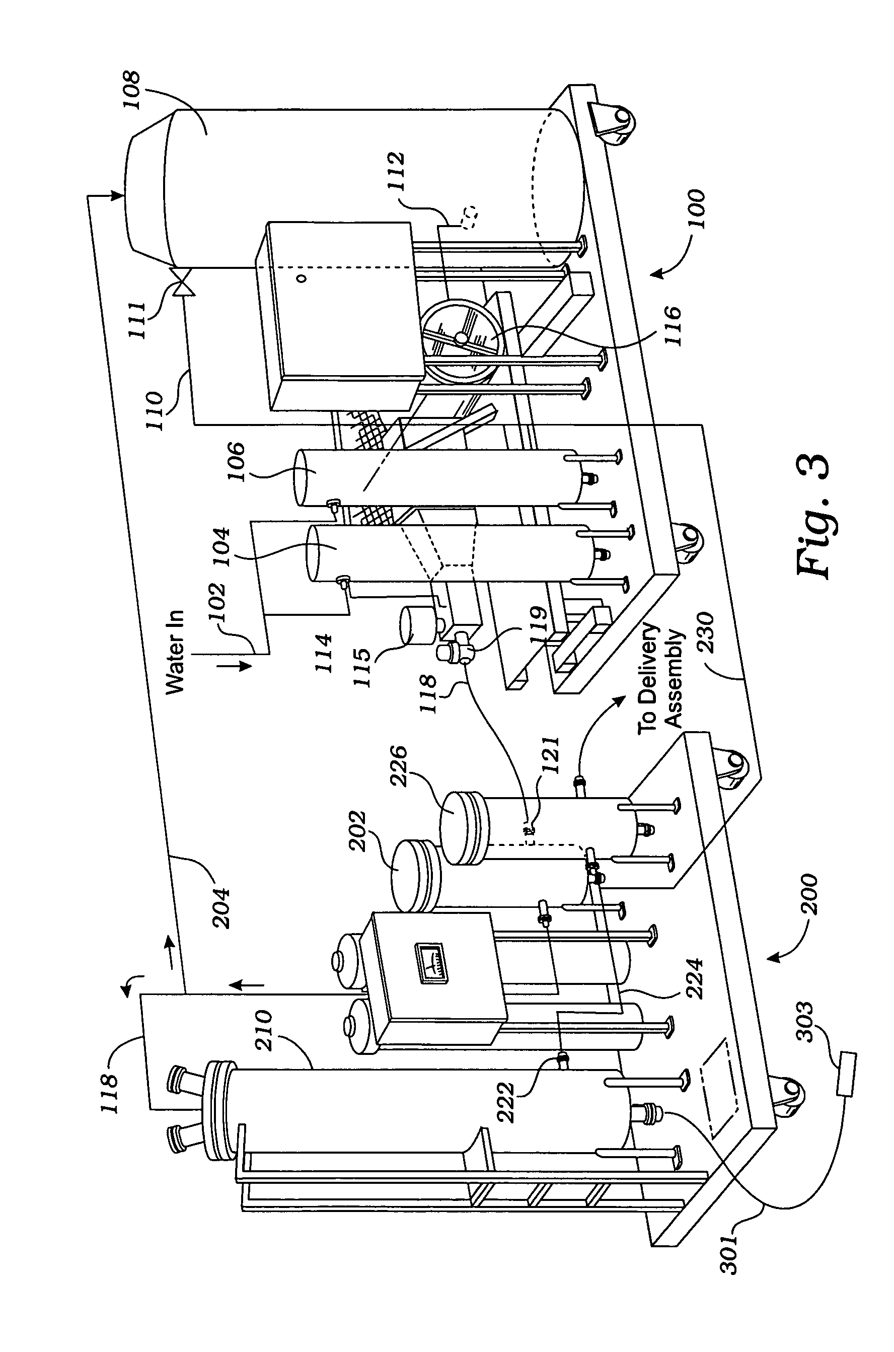
[0024]By placing one or more delivery nozzles at a treatment site, oxygen levels at the site advantageously may be maintained or increased by delivering oxygen-enriched water to the site. For example, in a wastewater treatment reactor, oxygen-enriched water may be added to the reactor contents to help support biological degradation activity, reduce biochemical oxygen demand, etc. Advantageously, the water used to supply the oxygen-enriched fluid supply system is filtered to minimize the risk of the delivery nozzle becoming clogged by particulate matter. The water used to supply the system may come from any source, e.g., a municipal water source; a river, lake, or other reservoir; the treated water effluent of a wastewater treatment operation; the supply of wastewater to be treated, etc.

Problems solved by technology

When the loading of organic matter exceeds this assimilative capacity, the water resource is impaired for this reason.
Pollution, or contamination, of water is a serious problem throughout the world, particularly in the United States.
Industrial entities may discharge liquid or two-phase (liquid / solid) waste indirectly or directly into the environment, such as into rivers and lakes, contaminating the water supply and harming the environment, fish and wildlife.
Air pollution is also a problem, particularly industrial air pollution, because airborne contaminants may be collected by rainfall and runoff into bodies of water.
In addition, wastewater and air pollution typically emit an undesirable odor from the contaminants, which may be a result of insufficient wastewater treatment or inefficient industrial systems (e.g., inefficient combustion, chemical reactions or processes, etc.) creating such contaminants.
Municipalities also produce considerable waste.
Particularly, combined sewer overflows (CSOs), sanitary sewer overflows (SSOs), and stormwater discharges can create significant problems.
Sanitary sewers may overflow for a variety of reasons, such as inadequate or deteriorating systems, broken or leaky pipes, and / or excessive rain or snowfall infiltrating leaky pipes through the ground.
Finally, storm water runoff adds to the problem, as pollutants are collected en route to rivers, streams, lakes, or into combined and sanitary sewers.
Although the discussion has been limited to industrial and municipal waste, contamination may arise from a variety of sources and accumulate in various site specific and non-site specific locations.
For example, agricultural waste, pesticides and fertilizers create site specific water contamination, such as in ponds, streams, irrigation, ground water and drinking water for the animals and people.
Such mixers generally have relatively low initial capital costs, but often require substantial amounts of energy to operate.
The performance of fine bubble aeration degrades over time if regular maintenance is not used.
Thus, much expense may be saved by enhancing the operating efficiency of existing facilities in response to increased demand for wastewater treatment.
One particular target has been the substantial electricity and other energy costs associated with the operation of conventional systems for aerating wastewater.

Method used


Image

  • Apparatus for oxygenating wastewater
  • Apparatus for oxygenating wastewater
  • Apparatus for oxygenating wastewater

Examples


Embodiment Construction

[0039]The description below illustrates certain specific embodiments or forms that depict various aspects of the present invention. For the sake of clarity, not all features of an actual implementation are described in this specification. It should be appreciated that in connection with developing any actual embodiment of the present invention many application-specific decisions must be made to achieve specific goals, which may vary from one application to another. Further, it should be appreciated that any such development effort might be complex and time-consuming, but would still be routine for those of ordinary skill in the art having the benefit of this disclosure.

[0040]For the sake of clarity and convenience, the various embodiments are described herein in the context of applications generally involving municipal wastewater treatment, including treatment of CSOs, SSOs, and storm water discharges. However, the present invention may also be useful in other applications, such as ...


PUM

PropertyMeasurementUnit
Diameteraaaaaaaaaa
Capillary waveaaaaaaaaaa

Abstract

A method and apparatus creates gas-enriched fluid that is used to treat wastewater. In one embodiment, the wastewater is withdrawn from a supply of wastewater to be treated, and the wastewater is delivered in an atomized manner to a vessel pressurized with gas to form gas-enriched wastewater. The gas-enriched wastewater is then delivered to the supply of wastewater to be treated.

Description

FIELD OF THE INVENTION[0001]The present invention relates generally to a system and method for gas-enriching water and, more particularly, to a system and method for providing large volumes of oxygen-enriched water to a reservoir, tank, pond, stream, etc. to help meet its biochemical oxygen demand.BACKGROUND OF THE INVENTION[0002]This section is intended to introduce the reader to various aspects of art which may be related to various aspects of the present invention which are described and / or claimed below. This discussion is believed to be helpful in providing the reader with background information to facilitate a better understanding of the various aspects of the present invention. Accordingly, it should be understood that these statements are to be read in this light, and not as admissions of prior art.[0003]Any natural waterway has the ability to assimilate organic matter. When the loading of organic matter exceeds this assimilative capacity, the water resource is impaired for ...

Claims


Application Information

Patent Timeline
IPC IPC(8): C02F3/00B01D36/02B01F1/00B01F3/04B01F5/20B01F13/06C02F1/76C02F1/78C02F3/24C02F3/26C02F9/00
CPCB01F3/0473B01F3/0876C02F3/24C02F3/26C02F2203/008C02F2103/06C02F2201/008Y02W10/10B01F23/234B01F23/454
Inventor SPEARS, J. RICHARDCRILLY, RICHARDRYDMAN, RAYGESSERT, JAMESMYRICK, STEVE
Owner WAYNE STATE UNIV
Learn More