
Device for fastening poles, posts, masts or the like in the ground, and method for manufacturing a fastening device

Inactive Publication Date: 2006-03-07
KRINNER INNOVATION
View PDF23 Cites 47 Cited by
  • Summary
  • Abstract
  • Description
  • Claims
  • Application Information

AI Technical Summary

Benefits of technology

[0007]The object of the present invention is therefore to provide a fastening device for poles, posts, masts or the like for driving or screwing into the ground, which, essentially under all conditions and with the use of as little material as possible, affords great stability and thus allows secure anchoring in the ground and also affords safe and easy handling during driving-in or screwing into and out of the ground. Another object of the present invention is to provide a method for manufacturing such a fastening device for fastening poles, posts, masts or the like in the ground, in particular for manufacturing a ground peg with a basic body, which method is inexpensive in the manufacture of the basic body of the fastening device and requires the use of a small amount of material.
[0008]The present invention includes a method for manufacturing a device for fastening poles, posts, masts or the like in the ground, in particular a ground peg, and in particular to manufacture a fastening device according to the present invention having a basic body which optionally includes at least one part portion provided with a screw-like or spiral-like thread, and has substantially a cone-shaped basic shape with at least one conical part portion. The method includes the basic body being hammered, forged or worked into the basic shape from an essentially cylindrical tube. If desired, the screw-shaped or spiral-shaped thread can then be attached to the basic body at least in one part portion, in particular by welding on a correspondingly prefabricated shaped part. The basic shape of the basic body can be designed in an essentially acute-angled and cone-shaped manner as an anchoring portion, which makes possible easy driving-in or screwing-in.
[0009]The hammering into shape of an essentially cylindrical tube to manufacture the basic body of the fastening device according to the present invention affords an advantage that the deforming forces acting on the cylindrical tube are introduced into the tube both axially and radially by shaping hammer parts running axially around the tube, as a result of which relatively great deformation of the tube can be achieved. In contrast, when the tube is pressed into shape by axial pressing-in in a die, only axial forces act on the tube, by means of which the tube could be upset. The tube-hammering method according to the present invention for cone-shaped basic shapes of the basic body of the fastening device is consequently particularly reliable and safe.

Problems solved by technology

In this connection, the manufacture of parts by casting or milling is relatively complicated and costly, and the manufacture of shaped parts does not allow 100% utilization of the starting material, which likewise contributes to increasing the cost of manufacture.
In addition, the joints, at which the individual shaped parts are welded, adhesively bonded or pressed together, may bring about a weakening of the stability of the basic bodies of the corresponding fastening devices.
As the fastening device, and in particular the anchoring portion, according to German Utility Model 93 13 258.1, is made up of a number of parts welded together, problems of strength may arise in particular in the region of the connection between the threaded portion and the displacement portion during screwing-in and out or in the event of forces acting on the fastening device.
Moreover, the threaded portion of the anchoring portion, which is in the form of a cast part with a solid core, requires the use of a great deal of material.
The relatively obtuse cone angle, which remains constant over the entire anchoring portion, makes screwing the fastening device into the ground more difficult on account of radial forces which arise, and, owing to the cone shape, does not allow secure anchoring of the fastening device in the ground because forces, such as those caused by shaking movements, arising radially on account of the obtuse cone angle, lead to the anchoring portion being loosened from the ground.
These processes are relatively cost-intensive and thus expensive on account of necessary preliminary work.
While it is true that an anchoring portion manufactured in this way does not have any stability-reducing joints, it nevertheless has to be made from solid material in order to achieve the stability required.

Method used


Image

  • Device for fastening poles, posts, masts or the like in the ground, and method for manufacturing a fastening device
  • Device for fastening poles, posts, masts or the like in the ground, and method for manufacturing a fastening device
  • Device for fastening poles, posts, masts or the like in the ground, and method for manufacturing a fastening device

Examples


Embodiment Construction

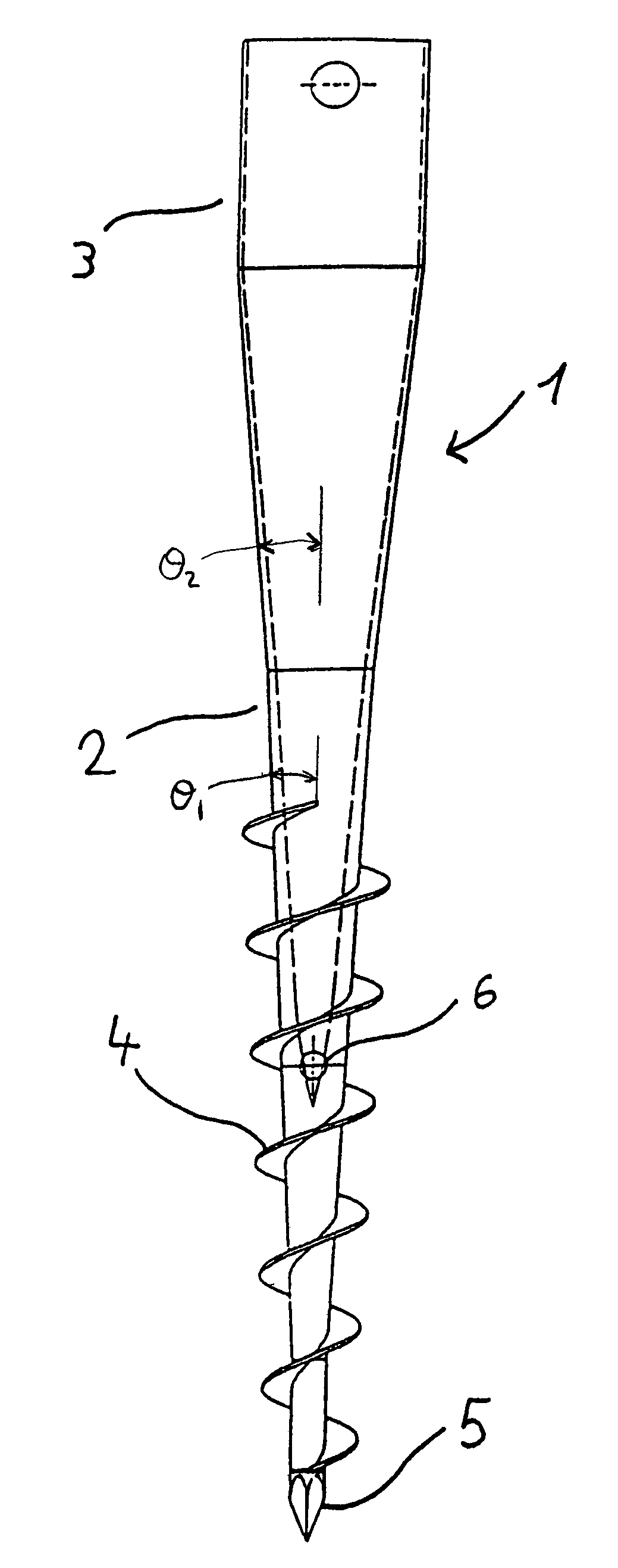
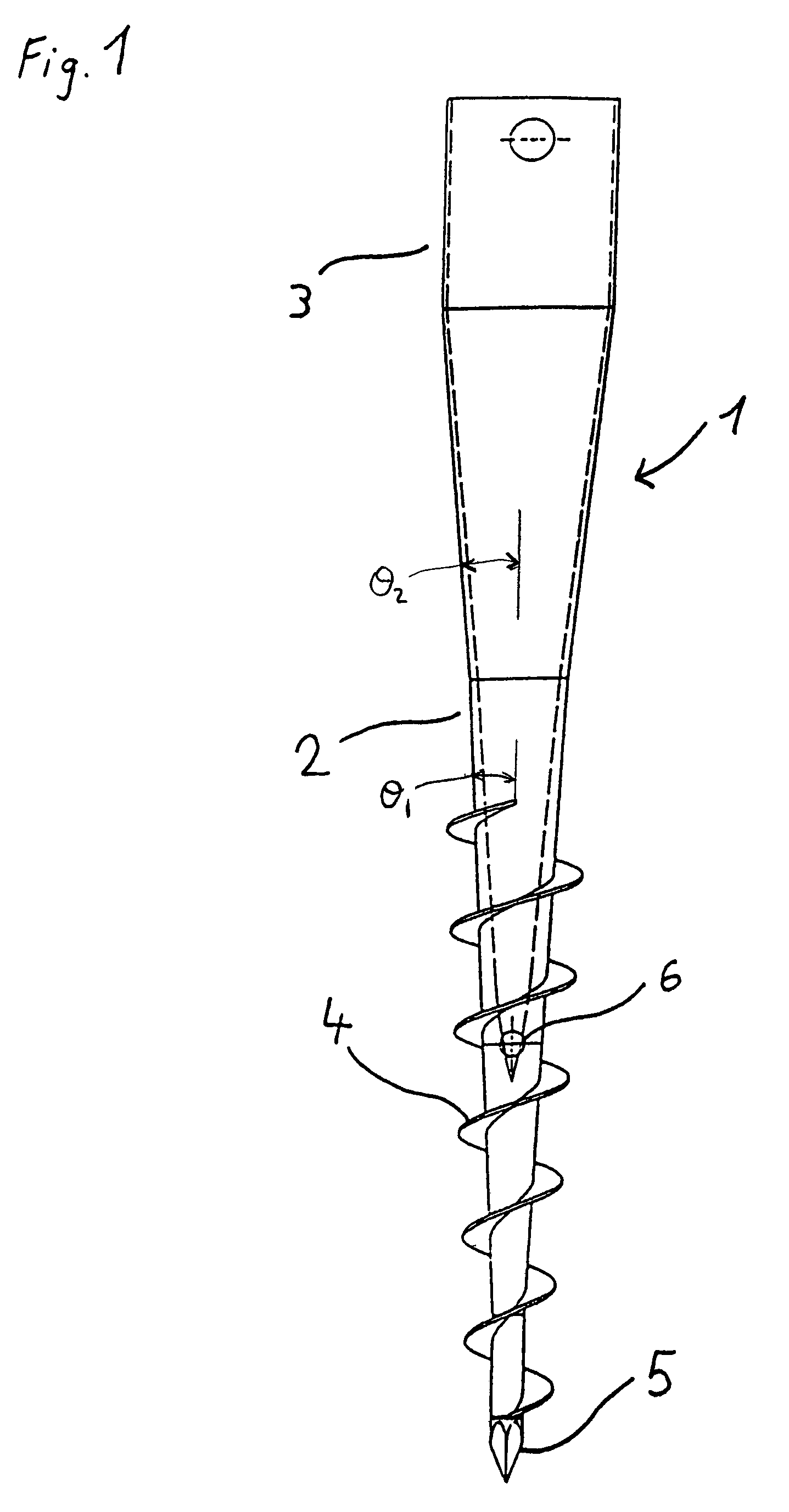
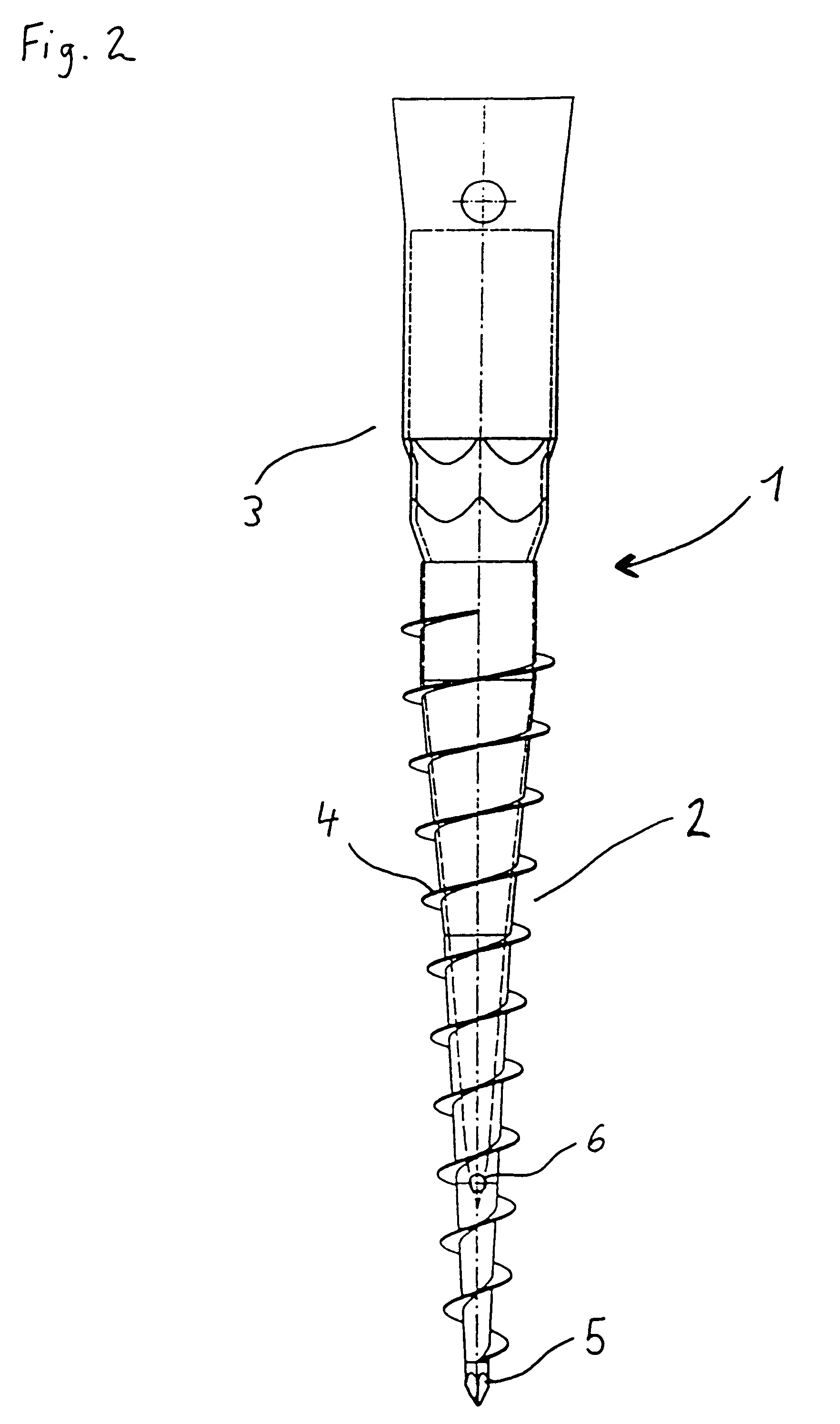
[0043]FIGS. 1 and 2 show two preferred embodiments of the fastening device according to the present invention with a thread for screwing into the ground and out of it again. All details relating to these two figures, with the exception of those which concern the thread, can also apply for the fastening devices according to the present invention without a thread for driving into the ground.

[0044]FIG. 1 shows a first preferred embodiment of the fastening device according to the present invention with a thread.

[0045]The fastening device has a basic body 1 with an anchoring portion 2 and a holding portion 3, the anchoring portion 2 and the holding portion 3 being formed in one piece. The anchoring portion 2 is designed as an essentially acute-angled displacement body and is divided into two part portions of different conicity. The first cone-shaped part portion in the screwing-in direction having a more acute cone angle θ1 than the cone angle θ2 of the second conical part portion in the...


PUM


Abstract

A method for manufacturing a device for fastening poles, posts, masts or the like in the ground and a fastening device with a basic body are described, it being possible, but not essential, for at least one part portion of the basic body to be provided with a screw-like or spiral-like thread, and the basic body essentially having a cone-shaped basic shape with at least one conical part portion. According to the method of the present invention, the basic body is hammered into the basic shape from an essentially cylindrical tube. The fastening device has a holding portion, and an anchoring portion designed in one piece which, if provided with a thread, has at least two part portions of different conicity. The holding portion and essentially the anchoring portion are hollow throughout.

Description

BACKGROUND OF THE INVENTION[0001]The present invention relates to a device for fastening poles, posts, masts or the like in the ground and a method for manufacturing a fastening device.[0002]Fastening devices for poles, posts, masts or the like for driving or screwing into the ground are in most cases manufactured by metal casting or welding together individual prefabricated shaped parts. In this connection, the manufacture of parts by casting or milling is relatively complicated and costly, and the manufacture of shaped parts does not allow 100% utilization of the starting material, which likewise contributes to increasing the cost of manufacture. In addition, the joints, at which the individual shaped parts are welded, adhesively bonded or pressed together, may bring about a weakening of the stability of the basic bodies of the corresponding fastening devices.[0003]A fastening device is known from German Utility Model 93 13 258.1. This has a threaded portion, which can be screwed ...

Claims


Application Information

Patent Timeline
IPC IPC(8): F16M13/00E04H12/22
CPCE04H12/2223E04H12/2215
Inventor KRINNER, KLAUSTHURNER, GUENTHER
Owner KRINNER INNOVATION
Learn More