
Programmable logic resource with data transfer synchronization

a synchronization and data transfer technology, applied in the field can solve the problems of clock latency, increase achieve the effects of reducing the area and thus the cost of programmable logic resources, reducing the latency associated, and facilitating the user's logic design

Active Publication Date: 2006-02-21
TAHOE RES LTD
View PDF3 Cites 37 Cited by
  • Summary
  • Abstract
  • Description
  • Claims
  • Application Information

AI Technical Summary

Benefits of technology

[0007]In accordance with the invention, a more time-efficient and area-efficient approach in synchronizing the transfer of data into programmable logic resources without the use of phase synchronizers is provided.
[0011]Implementing a reset register to synchronize the transfer of data in accordance with the invention has several advantages over using a phase synchronizer. The reset register eliminates the latency associated with storing data in the FIFO buffer of the phase synchronizer. The invention therefore makes it easier for a user to design logic in, and can potentially save logic elements used in, the programmable logic resource core circuitry. In addition, less logic is needed to implement the reset register, which decreases the area and thus cost of the programmable logic resource.

Problems solved by technology

There are several limitations with using phase synchronizers to synchronize the transfer of data into programmable logic resources.
Implementing a phase synchronizer results in clock latency.
In addition, the phase synchronizer requires a large amount of logic to implement, which increases the area and thus cost of the programmable logic resource.

Method used


Image

  • Programmable logic resource with data transfer synchronization
  • Programmable logic resource with data transfer synchronization
  • Programmable logic resource with data transfer synchronization

Examples


Embodiment Construction

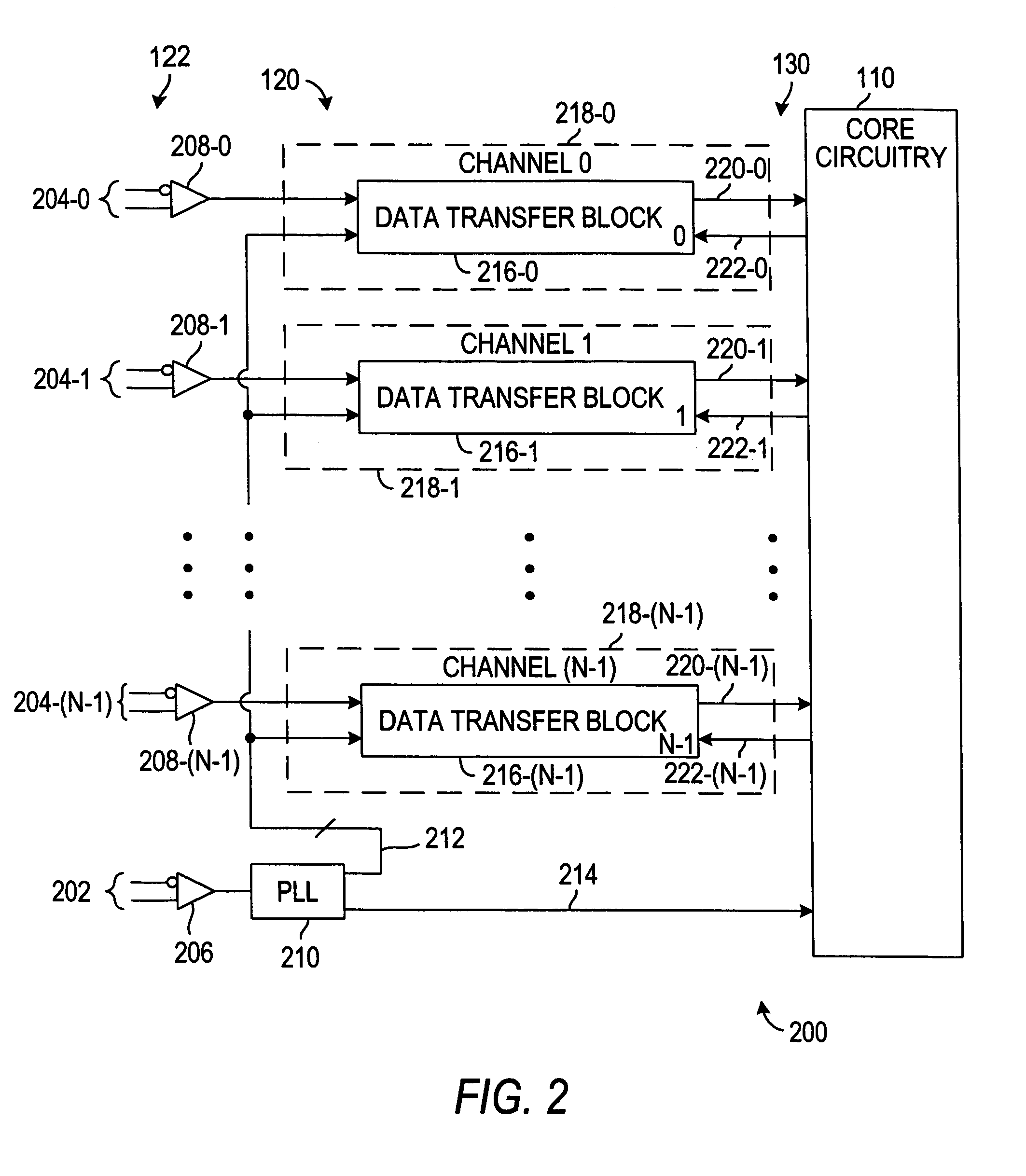
[0020]An illustrative programmable logic resource 100 constructed in accordance with the invention is shown in FIG. 1. Programmable logic resource 100 is an integrated circuit that includes programmable logic resource core circuitry 110 and input-output (I / O) circuitry 120. Programmable logic resource core circuitry 110 can be typical programmable logic circuitry of any of several known types and constructions. I / O circuitry 120 can be any suitable interface that allows the transfer of data between programmable logic resource core circuitry 110 and circuitry external to programmable logic resource 100. I / O circuitry can be, for example, high speed serial interface circuitry implemented in an intellectual property block.

[0021]Although the invention is described herein primarily in the context of providing circuitry for synchronizing the transfer of data on a programmable logic resource for clarity, the circuitry can be provided on any suitable device such as, for example, an applicat...


PUM


Abstract

A more time-efficient and area-efficient approach is provided to synchronize the transfer of data into programmable logic resources. A programmable logic resource core clock and a reset signal are routed to a reset register that controls the reset of a dynamic phase alignment circuit and a data realigner. The dynamic phase alignment circuit includes a phase-locked loop circuit, a J counter, and a deserializer. When the output signal of the reset register transitions from logic 1 to logic 0, the J counter begins to count and sets an enable signal accordingly. The enable signal, which controls the output of synchronized parallel data from the deserializer, is therefore phase associated with the programmable logic resource core clock. The synchronized parallel data is input to a data realigner which outputs the data based on the programmable logic resource core clock for input to the programmable logic resource core circuitry.

Description

BACKGROUND OF THE INVENTION[0001]This invention relates to programmable logic resources. More particularly, this invention relates to synchronizing the transfer of data into programmable logic resources.[0002]A programmable logic resource is a general-purpose integrated circuit that is programmable to perform any of a wide range of logic tasks. Known examples of programmable logic resource technology include programmable logic devices (PLDs), complex programmable logic devices (CPLDs), erasable programmable logic devices (EPLDs), electrically erasable programmable logic devices (EEPLDs), and field programmable gate arrays (FPGAs).[0003]Input-output (I / O) circuitry is provided to facilitate the transfer of data into programmable logic resources. The I / O circuitry serves as an interface between programmable logic resource core circuitry and circuitry external to the programmable logic resource.[0004]Data is often transferred from external circuitry to programmable logic resource core ...

Claims


Application Information

Patent Timeline
Patent Type & Authority Patents(United States)
IPC IPC(8): G01R27/28G01M19/00G06F1/04G01M99/00
CPCG06F1/24G06F1/12
Inventor KABANI, MALIKLUI, HENRY
Owner TAHOE RES LTD
Learn More