
Underwater mine countermeasure warfare system

a mine countermeasure and warfare technology, applied in the field of underwater mine countermeasure warfare, can solve the problems of defeating the effectiveness of a new detonator, affecting the speed of the vehicle, and affecting the vehicle's ability to move quickly

Inactive Publication Date: 2006-02-21
TEXTRON INC
View PDF10 Cites 9 Cited by
  • Summary
  • Abstract
  • Description
  • Claims
  • Application Information

AI Technical Summary

Benefits of technology

[0006]The present invention substantially alleviates, if not altogether eliminates, the disadvantages of prior known vehicles utilized in mine countermeasure warfare, particular those utilized in underwater mine countermeasure warfare.
[0010]Several significant advantages are offered by the use of an air cushion vehicle over a flotation vehicle, whether of single or of multiple hull construction, such as greater maneuverability and speed, and, most importantly, the relative insensitivity of an air cushion vehicle to underwater shock. Relative high speeds in the order of 45 knots afford greatly decreased transit times in relocating from one operational zone to another, and the ability to operate in high seas further adds to the operational flexibility of the vehicle.
[0011]One critical operational requirement of an air cushion vehicle is that of avoiding any and all unnecessary weight. Since the vehicle is supported on a cushion of air beneath the platform, the heavier the vehicle becomes, the more difficult it is to generate the pressure required to lift the vehicle from the supporting surface. Thus, as weight is added to a given vehicle, more powerful and larger capacity lift engines and blowers are required to generate the necessary pressure, thereby rendering the vehicle more cumbersome and costly to operate.
[0012]In order to obtain full benefit of the advantages of an air cushion vehicle, it is necessary to have a magnetic field generating means which is both light in weight and yet capable of generating the maximum field strength possible. By eliminating the axial coils used in the predecessor vehicle, the heavy iron pipe cores are no longer required, thereby substantially reducing the weight of the improved coil system. In addition, the new coil configuration provides an increased magnetic field intensity due to the area within the rectangular frames, thereby enabling larger ships to be simulated and a wider lane to be swept. In addition, the maintainability of the system is greatly enhanced because all components are either on or above the platform of the vehicle. Further, since the coils can easily be removed, the vehicle is more adaptable for use in alternate missions.
[0013]Having briefly described the general nature of the present invention, it is a principal object thereof to provide an underwater mine warfare countermeasure system which effectively alleviates or eliminates the disadvantages of prior known under water mine warfare countermeasure systems, while at the same time retaining the significant advantages thereof.
[0014]Another object of the present invention is to provide an underwater mine warfare countermeasure system which utilizes a water borne vehicle, preferably an air cushion vehicle, as the primary support vehicle for a system which explodes submerged mines without damage to the support vehicle.

Problems solved by technology

In addition to mere contact between a vehicle and a mine, various techniques have been developed to cause the mines to explode remotely so that the vehicle suffers damage without actually contacting the mine.
However, with each new technological advance in the sophistication of detonating systems for mines, a countermeasure is soon developed for defeating the effectiveness of a new detonator.
A major problem with any system for simulating a condition to which a mine is responsive is that of bringing the simulating system into sufficiently close proximity to the mine to cause it to explode without damaging the vehicle used to transport the simulating system.
Unfortunately, the vehicle could travel at only a moderate speed, thereby impeding its ability to move quickly from one operational location to another; it had very limited maneuverability; and being in the water it was subject to underwater shock from exploding mines and therefore had to be operated at considerable distances from the mines, necessitating very high capacity magnetic field generating equipment.

Method used


Image

  • Underwater mine countermeasure warfare system
  • Underwater mine countermeasure warfare system
  • Underwater mine countermeasure warfare system

Examples


Embodiment Construction

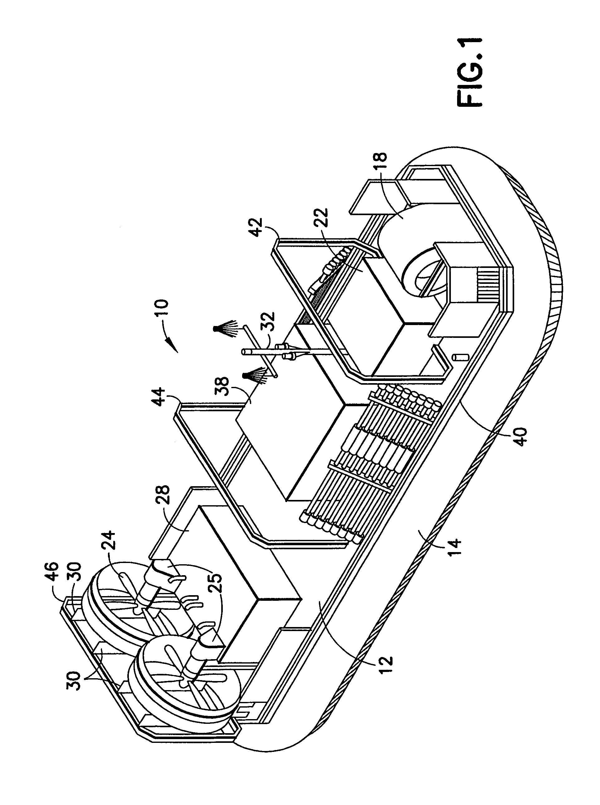
[0021]Referring now to the drawings, and particularly to FIGS. 1 through 4 thereof, the invention comprises a remotely controlled air cushion vehicle generally designated by the reference numeral 10, although as indicated above a flotation type vehicle could be substituted for the air cushion vehicle disclosed. The vehicle 10 is shown somewhat generally for illustrative purposes only and only those details of the vehicle which are necessary to an understanding of the invention are shown and described. Thus, the vehicle 10 comprises a platform 12 supported on a suitable hull 13 which constitutes the main structural hull of the vehicle. A peripheral skirt system 14 consisting of a bag of neoprene-coated nylon fabric is attached to the periphery of the platform 12 and extends downwardly therefrom to form an air chamber (not shown) between the underside of the platform 12 and any surface on which the vehicle is resting or over which it is traveling. The skirt system 14 provides a low dr...


PUM


Abstract

An underwater mine warfare countermeasure system is disclosed in which an air cushion vehicle carries a magnetic field generating system capable of generating a magnetic field pattern beneath the vehicle which extends sufficiently far from the vehicle in all directions to activate a magnetically responsive detonator in a mine while the vehicle is out of range of the explosive force of the mine. The magnetic field generating system generally is composed of a plurality of closed loop coils mounted on the deck of the vehicle, one coil being horizontal and in the plane of the deck, and another three being in vertical planes spaced along the length of the vehicle.

Description

BACKGROUND OF THE INVENTION[0001]This invention relates generally to the field of underwater mine countermeasure warfare, and more particularly to an underwater mine countermeasure warfare system utilizing an air cushion vehicle equipped with a magnetic sweep generator capable of emitting a magnetic field pattern for exploding submerged mines having magnetic field responsive detonators.[0002]It has long been well known in the field of both land and sea warfare to set mines in strategic locations which will explode at an appropriate moment to destroy vehicles and land vehicles which are within the explosive range of the mines. In addition to mere contact between a vehicle and a mine, various techniques have been developed to cause the mines to explode remotely so that the vehicle suffers damage without actually contacting the mine. For example, some mines are provided with acoustically responsive detonators which cause the mines to explode when the detonator detects a predetermined s...

Claims


Application Information

Patent Timeline
IPC IPC(8): B63G7/06
CPCB60V1/04B63G7/06B60V3/06
Inventor BENDER, GREGORY LOUISGLEASON, JAMES A.
Owner TEXTRON INC
Learn More