
Feeder assembly of vehicle sliding seat

a vehicle and sliding seat technology, applied in the direction of cables, cables, relatively moving parts, etc., can solve the problems of high parts cost, complicated structure, and concern about high parts cost, and achieve the effect of improving the workability of the case assembly

Active Publication Date: 2006-02-14
YAZAKI CORP +1
View PDF13 Cites 27 Cited by
  • Summary
  • Abstract
  • Description
  • Claims
  • Application Information

AI Technical Summary

Benefits of technology

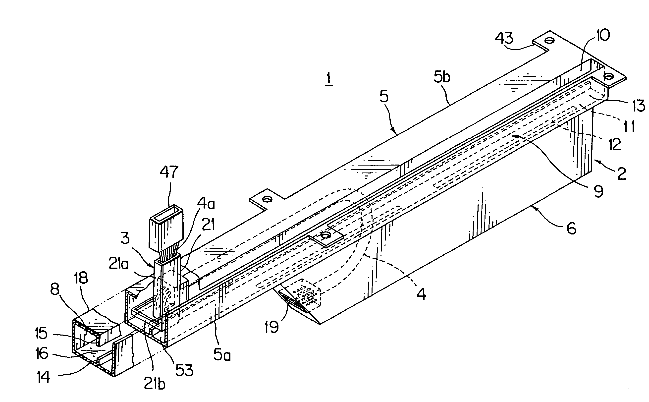
The present invention provides a feeder assembly for a vehicle sliding seat that prevents foreign substances, such as juice and sand, from entering the seat and damaging the wiring harness. The feeder assembly has a simple structure, low cost, and high versatility for different types of vehicles. It includes a case with a harness receiving section, a movable portion, and a wiring harness. The case has a slit through which the movable portion moves. The slit is connected to the case through a partition wall, which isolates the foreign substances from the harness receiving section. The movable portion has a harness pathway and a harness holder to arrange the electric wires flatly and smoothly in the seat. The feeder assembly also includes a hole for foreign substance ejection and a claw for easy fixing of the case to the vehicle body. The technical effects of the invention are to prevent foreign substances from entering the vehicle sliding seat and damaging the wiring harness, and to improve the workability and reliability of the feeder assembly.

Problems solved by technology

Moreover, since the upper wall 66 and top wall 75 of the case 62 are formed in complicated shape and the holding of the flat harness by the slider 63 makes the structure complicated, there is concern about high cost in parts.
Moreover, the use of the flat harness 64 as a circuit body makes the parts cost high and the limitation of the number of circuits causes a problem to narrow the versatility for every type of a vehicle.

Method used


Image

  • Feeder assembly of vehicle sliding seat
  • Feeder assembly of vehicle sliding seat
  • Feeder assembly of vehicle sliding seat

Examples


Embodiment Construction

[0039]Referring to the accompanied drawings, an embodiment of the present invention will be discussed in detail.

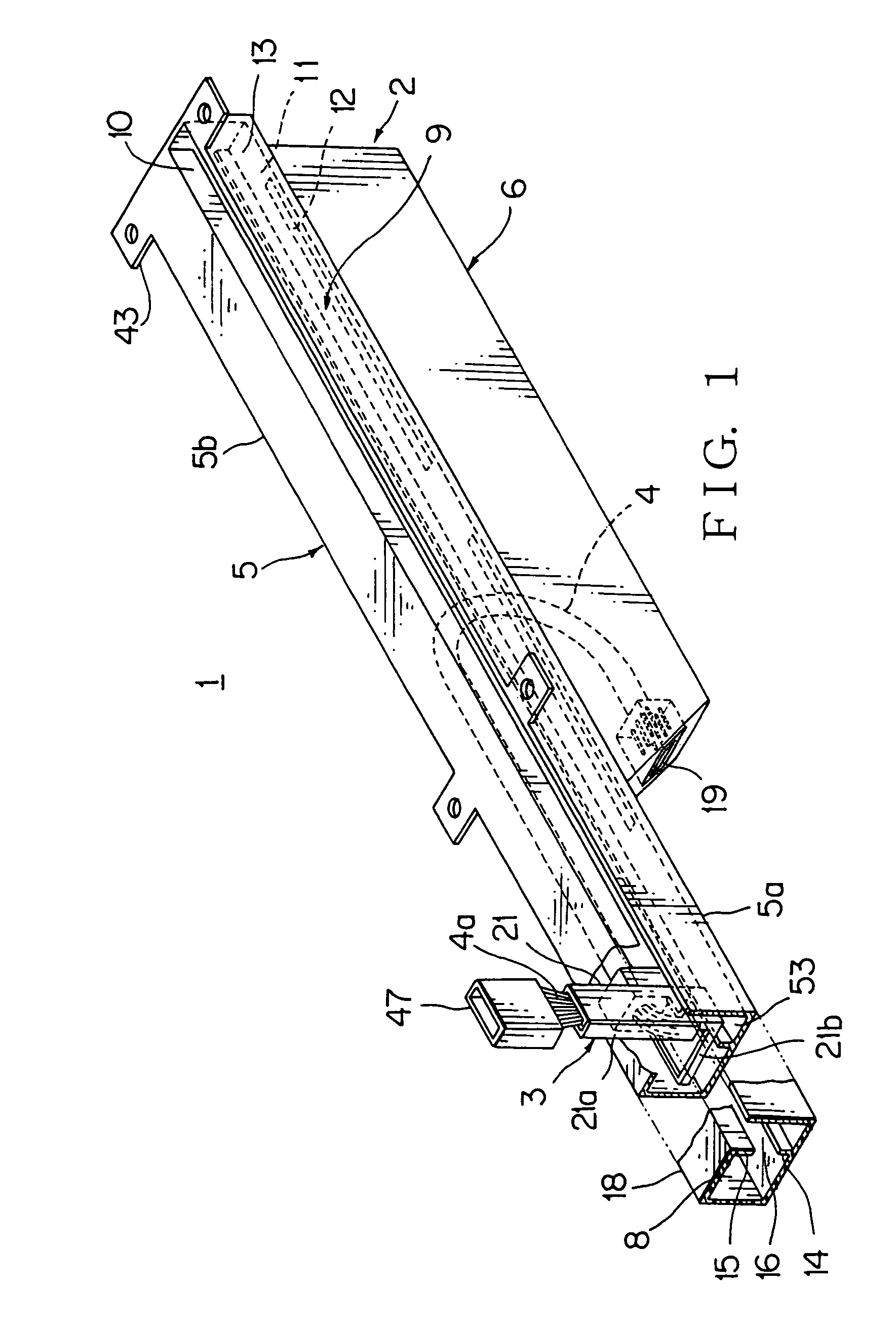
[0040]FIGS. 1 and 2 shows an embodiment of the feeder assembly of a vehicle sliding seat according to the present invention.

[0041]The feeder assembly 1 of the sliding seat comprises a case 2 made of a synthetic resin, a movable portion 3 made of a synthetic resin moving in the longitudinal direction of the case 2, a wiring harness 4 consisting of a plural of covered electric wires connecting the movable portion 3 and the case end.

[0042]The case 2 comprises a sliding portion 5 in generally rectangle pipe shaped, extending long accepting long sliding seat (long sliding stroke seat), and a harness receiving section 6 which is formed in width narrower than the sliding portion 5 and disposed at one side of the sliding portion 5.

[0043]The sliding portion 5 comprises a front half part 5a extending in generally rectangle piped shape, and a back half part 5b having a sliding space ...


PUM


Abstract

A feeder assembly 1 of a sliding seat comprising a case 2 having a harness receiving section 6, a movable portion 3 moving along the case, and a wiring harness 4, bent in the harness receiving section, supported one end by the movable portion and other end by the case, wherein a slit 10 is formed in the case 2 for the insertion of the movable portion 3, a foreign substance invasion space 53 is formed between the case 2 and a case bottom 11, and the space is isolated from the harness receiving section by partition walls 14 and 15. A foreign substance discharge hole 12 is disposed at the case bottom 11. The movable portion comprises a harness pathway 21 to make each electric wire 4a of the wiring harness 4 arrange flatly in parallel, and a harness holder 22 which bundles each electric wire in circular cross-section following the harness pathway. A clearance is disposed between the movable portion and the case so that the movable portion 3 positions with non-contact or almost non-contact of the case 3.

Description

BACKGROUND OF THE INVENTION[0001]1. Field of the Invention[0002]The present invention relates to a feeder assembly of a vehicle sliding seat for supplying electric power to auxiliary units in the vehicle sliding seat, aiming the prevention of foreign substance invasion and the smoothness of the sliding movement.[0003]2. Related Art[0004]A seat of a vehicle is provided with various auxiliary units such as a motor for sliding drive, a crew member detection sensor, and a heater. Various feeder assemblies of sliding seat have been proposed.[0005]FIGS. 11 and 12 show a conventional example of feeder assembly of a vehicle sliding seat. (refer to patent document 1)[0006]The feeder assembly 61 is provided with a generally rectangle pipe case 62, a slider 63 moving in the seat sliding direction of the case 62, and a flat harness 64. The flat harness is supported by the slider 63 at one end and fixed by the case end at the other end, bent to generally U-shaped in the case.[0007]The case 62 ha...

Claims


Application Information

Patent Timeline
Patent Type & Authority Patents(United States)
IPC IPC(8): B60N2/02B60N2/90B60N2/06B60N2/07B60R16/02H02G11/00
CPCB60N2/0224B60N2/0732B60N2002/0264B60N2/0264
Inventor TSUBAKI, AKIRAWAKAMATSU, HIROYUKIWADA, HIROFUMIMURAOKA, TADASHI
Owner YAZAKI CORP
Learn More