
Control system and method for continuous mixing of slurry with removal of entrained bubbles

a technology of slurry and slurry, which is applied in the direction of liquid degasification, separation processes, instruments, etc., can solve the problems of urea linkages in the polymer, limited resistance to applied load, and inability to recover the original shape slowly and accurately

Inactive Publication Date: 2006-02-07
MOBIUS TECH
View PDF46 Cites 33 Cited by
  • Summary
  • Abstract
  • Description
  • Claims
  • Application Information

AI Technical Summary

Benefits of technology

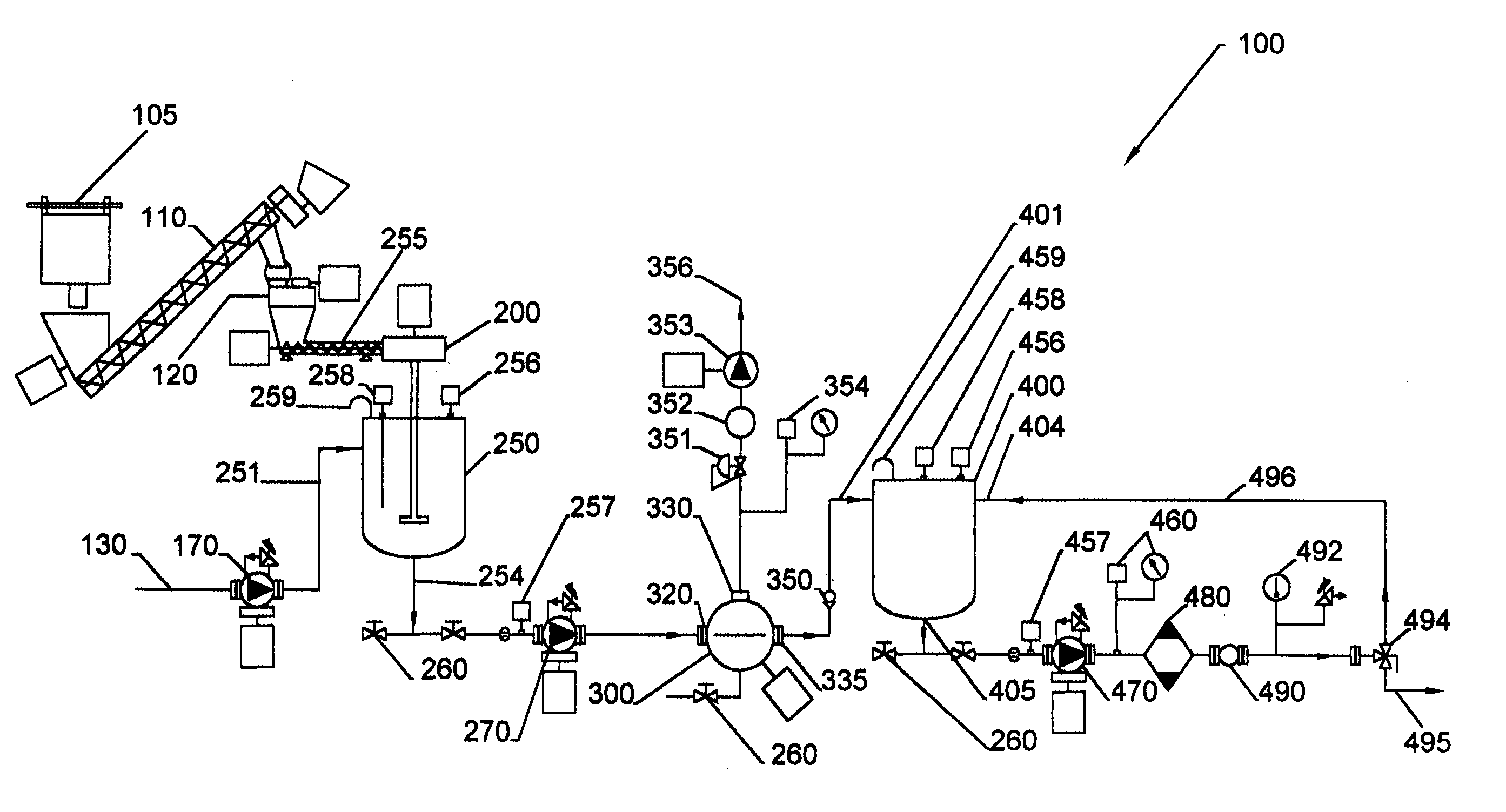
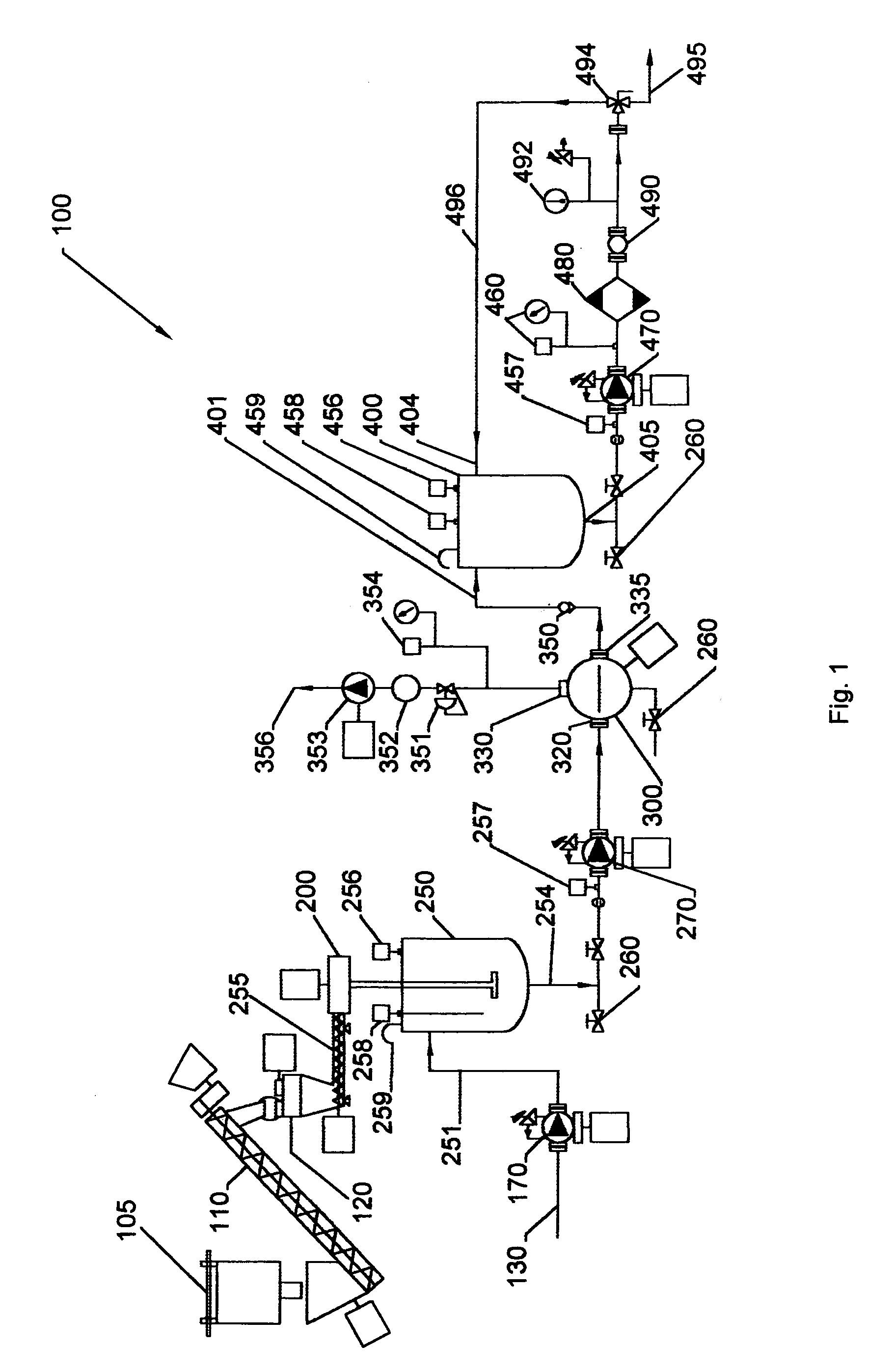
[0010]The present system comprises a control system and method for the continuous production of substantially bubble-free slurries of solid powders in liquids and for the delivery of such slurries at an accurately controlled concentration and flow rate. The system also comprises a method of controlling the process operation while providing accurate and stable slurry concentration and flow rate.
[0012]A feedback control system provides for continuous operation of the process with good control over the slurry concentration and flow rate. The description of the control process begins from the end of the process. The flow rate of the finished slurry is measured, for example by a mass flow meter, preferably by an in-line coriolis-effect mass flow meter. The flow rate measurement is used to control the rate of the pump that is drawing slurry from the bottom of the surge tank. The amount of slurry in the surge tank is measured, for example by a level sensor, preferably by a continuous ultrasonic level sensor. The level measurement is used to control the rate of the transfer pump that is drawing slurry from the bottom of the mix tank and delivering the slurry to the centrifuge. The amount of slurry in the mix tank is measured, for example by a level sensor, preferably by a continuous capacitance level sensor. The level measurement is used to control the reference rate of powder addition to the mixer. The actual rate of powder addition to the mixer is measured, for example by a scale, preferably by a loss-in-weight feeder. The actual rate of powder addition to the mixer is used to determine algebraically the required rate of polyol addition to the mix tank in order to provide the desired slurry concentration. The rate of the polyol supply pump is controlled in this way by the actual rate of powder addition to the mixer and the desired slurry concentration. This control method provides excellent control of the slurry concentration because powder and polyol are always added to the mix tank together in the desired ratio. The control method also provides excellent control of the slurry output flow rate, even if the rate of powder addition to the mix tank is varying.

Problems solved by technology

In addition to being reversibly deformable, flexible foams tend to have limited resistance to applied load and tend to have mostly open cells.
“Semi-rigid” or “semi-flexible” foams are those that can be deformed, but may recover their original shape slowly, perhaps incompletely.
This reaction also generates heat and results in urea linkages in the polymer.
Further, the slurry must be free of entrained bubbles because they create an undesirable irregular cell structure in the foam, including holes and splits.
Such a natural de-gassing process takes a long time because the slurry has a high viscosity, generally about 500 to 20,000 mPa-s.

Method used


Image

  • Control system and method for continuous mixing of slurry with removal of entrained bubbles
  • Control system and method for continuous mixing of slurry with removal of entrained bubbles
  • Control system and method for continuous mixing of slurry with removal of entrained bubbles

Examples


example 1

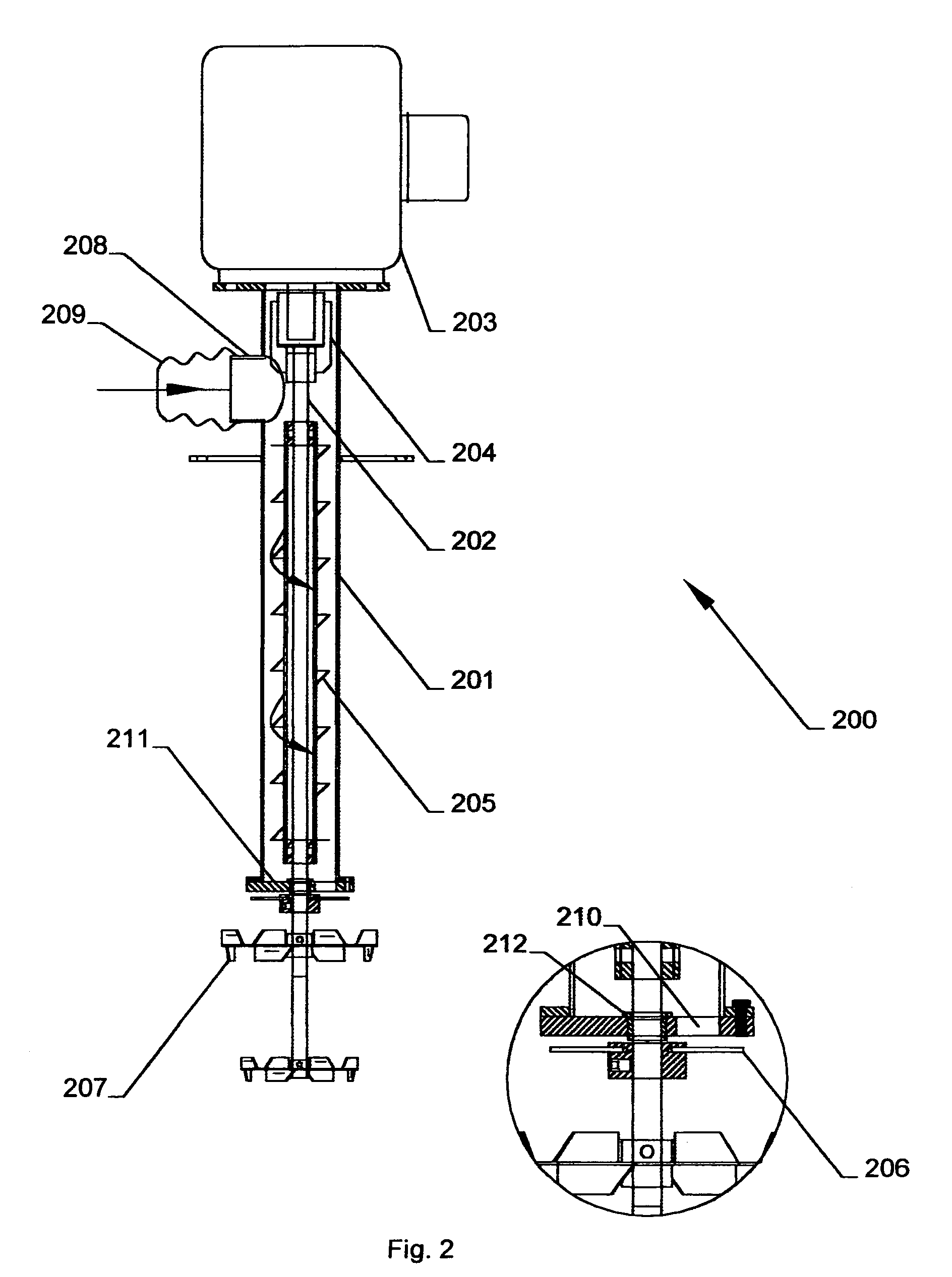
[0063]The process is started up by an initial partial fill of the mix tank 250 with a known amount of liquid sufficient to cover the outlet 210 of mixer 200. A known amount of powder is then added to the liquid in order to make a starting batch with the setpoint concentration. Once this initial batch has been made, the process may run continuously as disclosed above.

[0064]A mass of 83.5 kg of VORANOL 3010A polyether polyol from Dow Chemical Co. was initially charged to a 30-gallon mix tank. To this tank was added 16.7 kg of a powder of finely ground polyurethane foam with a maximum particle size of 250 microns. The initial batch was mixed thoroughly using the mixer shown in FIG. 2. The slurry obtained had a concentration of entrained air of about 10% by volume.

[0065]Using the process shown in FIG. 1 and the control method in FIG. 6, slurry was pumped from the mix tank, through the vacuum centrifuge and surge tank, and into a storage vessel. The concentration setpoint was 20 pphp (i....


PUM

PropertyMeasurementUnit
timeaaaaaaaaaa
viscosityaaaaaaaaaa
absolute pressureaaaaaaaaaa

Abstract

The present invention comprises a control system and method for the continuous mixing of slurry while removing entrained bubbles. The control system for continuous mixing of slurry with removal of entrained bubbles comprises a power and fluid rate control, wherein the powder and fluid rate control is coupled to a mixer through a powder feeder and a liquid pump. A fluid level control is coupled to the mixer and a surge tank, and a flow rate is coupled to the surge tank. The present invention also comprises a method for controlling the continuous mixing of slurry while removing entrained bubbles comprising providing a powder and fluid rate control, wherein the powder feeder and fluid rate control is coupled to a mixer through a powder feeder and a liquid pump. A fluid level coniol is coupled to the mixer and a surge tank and flow rate control is coupled to the surge tank.

Description

RELATED APPLICATIONS[0001]This application claims the benefit of U.S. Provisional Application No. 60 / 372,329, filed Apr. 11, 2002 and U.S. Provisional Application No. 60 / 372,270, filed Apr. 11, 2002.BACKGROUND[0002]1. Field of the Invention[0003]This invention relates to a control system and method for continuously preparing mixtures of powdered solids in liquids, removal of entrained bubbles from such mixtures, and for controlling such processes. The invention is particularly useful for the preparation of bubble-free slurries of finely ground polyurethane-foam particles in polyol, and for the preparation of new polyurethane articles that contain the finely ground polyurethane-foam particles.[0004]2. Background of the System[0005]“Polyurethane” (PUR) describes a general class of polymers prepared by polyaddition polymerization of polyisocyanate molecules and one or more active-hydrogen compounds. “Active-hydrogen compounds” include water and polyfunctional hydroxyl-containing (or “p...

Claims


Application Information

Patent Timeline
Patent Type & Authority Patents(United States)
IPC IPC(8): B01F15/02B01D19/00B01F3/12B01F7/00B01F7/16B01F13/10B01F15/00B01F15/04B29B7/84
CPCB01D19/0052B29B7/84B01F3/1221B01F3/1271B01F7/1625B01F13/1013B01F13/1044B01F15/00155B01F15/00837B01F15/0085B01F15/0251B01F15/0483B01D19/0063B01F15/00123B01F15/00883B01F15/00954B01F2003/0028B01F2013/1083B29B7/728B29B7/86B29B7/845B29B7/748B29B7/726B29B7/94B29B7/002B01F23/023B01F23/59B01F23/53B01F27/81B01F33/81B01F33/8305B01F33/83612B01F35/2112B01F35/511B01F35/513B01F35/531B01F35/181B01F35/71775B01F35/892B01F35/21
Inventor VILLWOCK, ROBERT DONALDCOCHRAN, JOSEPH RICHARDMARTEL, BRYAN LOUIS
Owner MOBIUS TECH
Learn More