Eureka AIR delivers breakthrough ideas for toughest innovation challenges, trusted by R&D personnel around the world.

Object extraction method, and image sensing apparatus using the method

a technology of object extraction and image sensing, applied in the field of object extraction method and image sensing apparatus using the method, can solve the problems of inability to realize conventional image processing methods, and inability to consider large calculation amount and long calculation time. to achieve the effect of high-speed search

Inactive Publication Date: 2006-01-31
CANON KK
View PDF19 Cites 71 Cited by
  • Summary
  • Abstract
  • Description
  • Claims
  • Application Information

AI Technical Summary

Benefits of technology

[0043]According to one mode of the present invention, it is an object of the present invention to provide an apparatus and method that can perform high-speed search processing of a specific object using information associated with the image sensing mode upon sensing an object.

Problems solved by technology

However, in the first and second methods, since the position or size of a specific object in an image or the hue or the like that reflects the illumination condition is not known in advance, the following problems are posed.
First, since similarity must be calculated using a plurality of standard patterns (images representing identical objects having different sizes, positions, hues, and the like), a considerably large calculation amount and long calculation time are required.
Third, the template size can be set in advance under only very limited image generation conditions. When the image generation conditions are not known, the same problem as the first problem is posed. Therefore, a very long calculation time is required for discriminating the presence / absence of a specific object, searching for an image including a specific object, and the like.
Furthermore, an application for searching a database of images sensed using an image sensing means for an image including an object intended to be generally the main object in the scene cannot be realized by conventional image processing methods that do not use any information upon image sensing.
The chromakey technique cannot be used outdoors due to strict limitations on the background, and also suffers a problem of color omission.
In the videomat technique, the user must accurately perform contour designation in units of pixels, thus requiring much labor and skill.
The technique using the difference from the background image cannot be normally applied when an image of only the background except for a specific object cannot be sensed (e.g., the object is huge), and the load on the user is heavy.
Since no image sensing conditions (camera parameters and external conditions such as illumination) are taken into consideration, discrimination errors of the region to be extracted from the difference data become very large unless the background image and the image including the object to be extracted are obtained under the same image sensing conditions and at the same fixed position.
Also, the technique described in Japanese Patent Publication No. 7-16250 is not suitable for extracting an image of an unknown object since it requires a color model of the object to be extracted.
Therefore, this method cannot be applied to a still object in an arbitrary background.
However, since the methods that use difference data from an image of only the background do not consider any image taking conditions (camera parameters and external conditions such as illumination) except for the technique described in Japanese Patent Laid-Open No. 6-253197, discrimination errors of the region to be extracted from difference data become very large unless the background image and the image including the object to be extracted are obtained under the same image taking conditions and at the same fixed position.
On the other hand, the method described in Japanese Patent Publication No. 7-16250 is not suitable for extraction of an image of an unknown object since it requires a color model of the object to be extracted.
Furthermore, the chromakey method cannot be used outdoors due to serious limitations on the background and also suffers a problem of color omission.
Also, in the videomat method, the contour designation operation must be manually and accurately performed in units of pixels, thus requiring much labor and skill.
The method of detecting regions segmented by a boundary line by detecting the boundary line by differential calculations can hardly be applied to an object having a complex texture pattern, and offers no stable and versatile boundary line detection processing scheme.
However, in the former example, since templates or models having different sizes must be prepared for a target image in correspondence with changes in size of a specific object in an image to perform matching in units of regions of the image, a very large memory capacity and a very long calculation time for feature vector extraction and matching with models are required.
In the latter example, it is generally difficult to stably cut out an action extraction portion on the basis of the luminance level of a projection component of an image.
Also, after motions at the respective points are tracked, it is difficult to interpret the motions at the respective points as one action category by combining such motion information, except for a simple action.
Furthermore, in constructing an image sensing apparatus or system, since the image sensing means does not have any command communication means for externally controlling the image sensing mode upon extraction of an object or any image sensing parameter control function required upon sensing an image for object extraction, image sensing conditions optimal to image extraction cannot be set.
Therefore, the image sensing conditions cannot be optimally set in correspondence with image taking situations such as a change in illumination condition, the presence / absence of object motions, the presence / absence of motions of the image sensing means itself, and the like for the purpose of image extraction.
However, again, an image sensing system cannot set optimal image sensing conditions to image extraction since an image sensing unit has neither a command communication control unit for appropriately controlling the image sensing mode from an external device upon extracting a specific object image nor a control function of the image sensing parameters required for sensing an image used for extracting a specific object image.
Therefore, the image sensing conditions cannot be optimally set in correspondence with image taking situations such as changes in illumination conditions, the presence / absence of object motion, the presence / absence of motions of the image sensing unit itself, and the like.
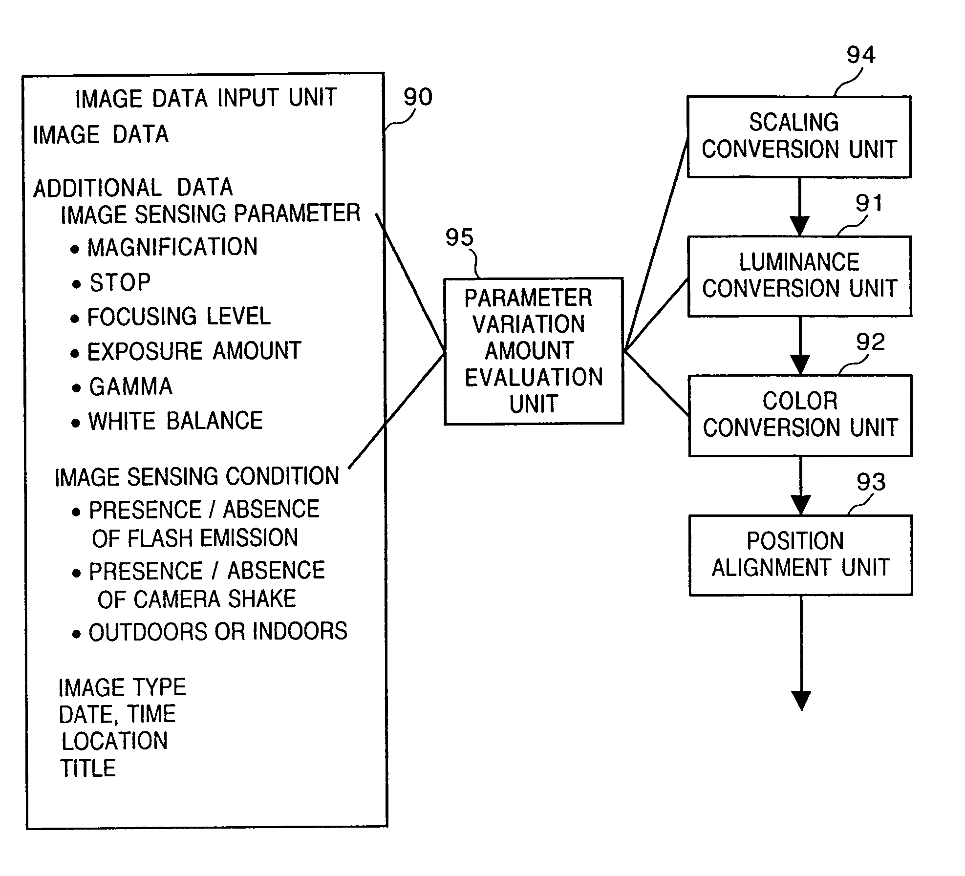
In particular, optimal image sensing conditions such as the field angle, focusing, illumination conditions (the presence / absence of flash emission), and the like for a designated object cannot be automatically or interactively set.
However, such function cannot be realized since communication control and image sensing control systems for performing such setting operation between the camera and the terminal device have not been established yet.

Method used


Image

  • Object extraction method, and image sensing apparatus using the method
  • Object extraction method, and image sensing apparatus using the method
  • Object extraction method, and image sensing apparatus using the method

Examples


first embodiment

[0303]The first embodiment that uses images having different image sensing conditions will be explained. In this embodiment, as the control of the image sensing condition for image extraction, the focusing state is controlled by controlling the layout of the imaging optical system under the condition that the magnification is constant.

[0304]FIG. 10 is a block diagram showing the arrangement of principal part of a system of this embodiment. Reference numeral 201 denotes an image sensing unit arranged as the image input unit; and 202, an imaging optical system. Reference numeral 203 denotes a drive control unit for the imaging optical system. The unit 203 comprises a zoom motor, a focusing motor, a stop system control system, a shutter speed control unit, and the like.

[0305]Reference numeral 204 denotes an image sensor (typically, a CCD image sensing element); and 205, an image sensing parameter measurement control unit, which comprises a lens layout measurement unit (not shown; e.g.,...

second embodiment

[0340]an image sensing apparatus that uses images having different image sensing conditions will be described below with reference to FIG. 12.

[0341]In this embodiment, after an initial contour is extracted from two images having different focusing states as in the first embodiment, background image region removal processing (step S39) using the selection / indication unit 213 (e.g., a mouse) is interactively performed for a region in the initial contour. In this case, the processing mode automatically shifts from the initial contour extraction mode to the background image region removal mode.

[0342]When the image in the contour is displayed, the image may be normalized and displayed by appropriately scaling the image size to have a predetermined size independently of the extracted image size. In the background removal processing, the type of feature of image data used for discriminating the background image region, and the allowable range of the attribute value are set in advance using...

third embodiment

[0345]an image sensing apparatus that uses images having different image sensing conditions will be explained below.

[0346]In this embodiment, by controlling the diameter of the stop or the shutter speed of the image sensing unit (step S443), a plurality of images having different exposure conditions are sensed (step S444) and are normalized by extracting comparison (difference) data therefrom (step S445). Thereafter, the processing including the setting operation of the initial contour to image extraction is performed.

[0347]FIG. 13 shows the processing flow of this embodiment. In particular, in this embodiment, the normalization processing of the luminance levels of two image data is performed before comparison data is extracted. More specifically, one of two image data is normalized by a maximum luminance value (to be described below) of reference image data, so that the maximum luminance value of luminance levels having frequencies equal to or larger than a predetermined value in ...


PUM


Abstract

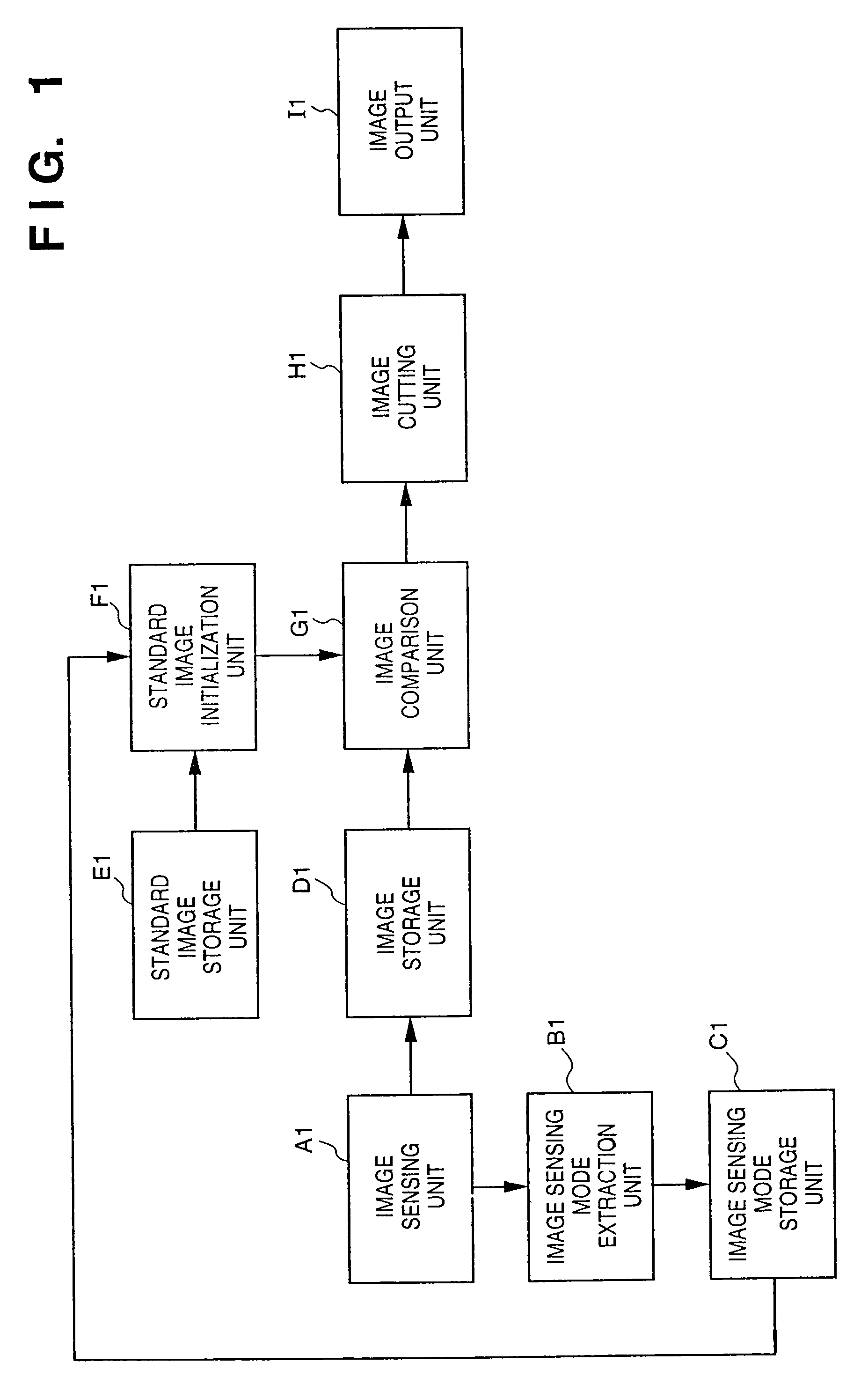
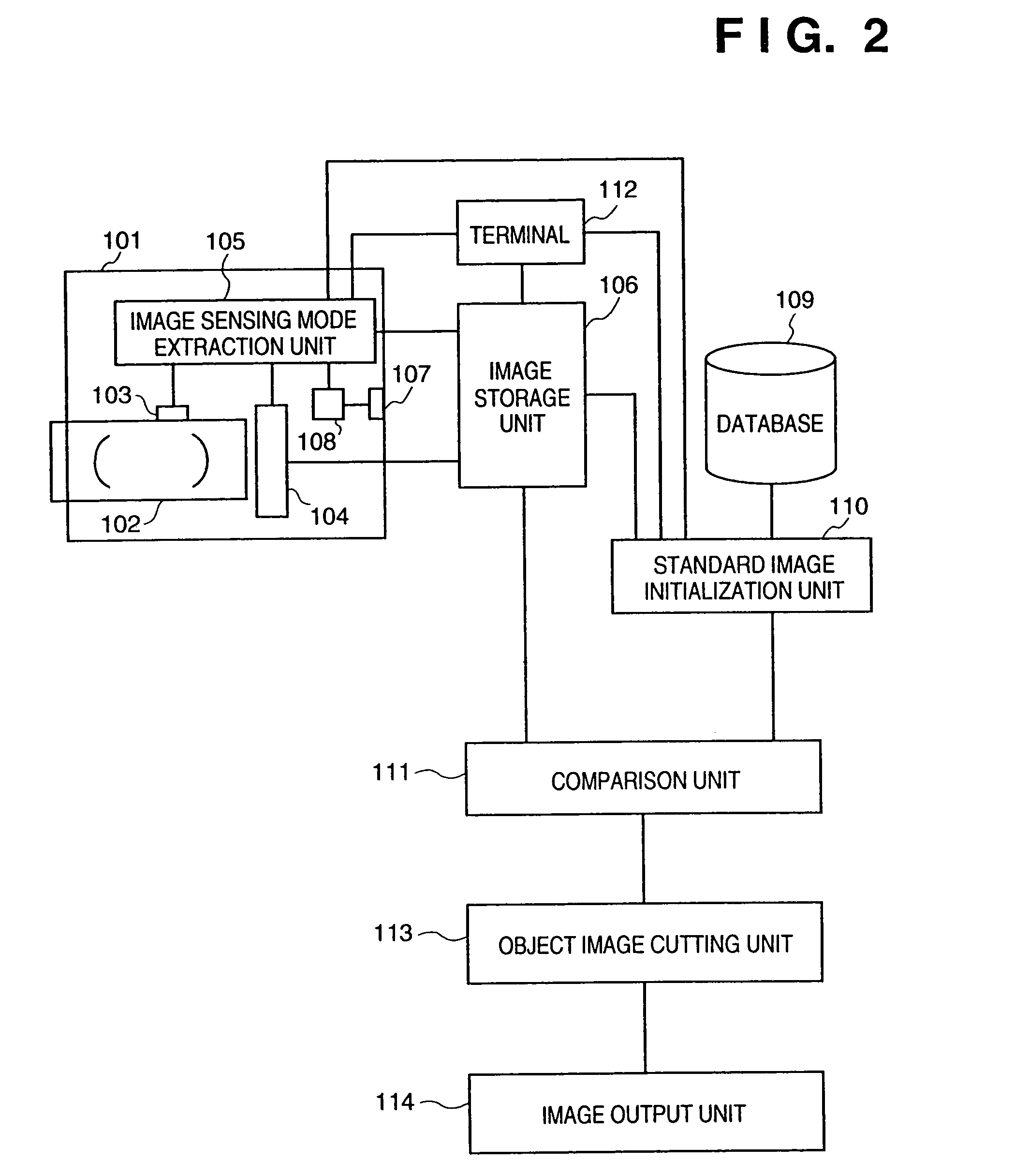
This invention provides an object extraction method for performing processing for extracting and cutting out a specific object from a sensed image at high speed, and an image sensing apparatus using the method. In this invention, in a method of extracting an object by comparing a sensed image and a standard image, a focusing signal, focal length data, visual axis direction data, and illumination conditions are detected, and the initial size, initial position, or initial color of the standard image is changed on the basis of the detection results, and extraction is started under optimal conditions. In a method of extracting a specific object from the background image, the background image is converted into an image having the same conditions as those of the object image. From a plurality of images obtained under different image sensing conditions, the contour of the object is accurately obtained at high speed. In an object extraction method using a template, the size of the template is determined on the basis of the object distance, object size, or the like.

Description

[0001]This is a divisional application of U.S. patent application Ser. No. 08 / 742,206, filed on Oct. 31, 1996, now U.S. Pat. No. 6,636,635, entitled “Object Extraction Method And Image Sensing Apparatus Using The Method.” now allowed, which is incorporated herein in its entirety.BACKGROUND OF THE INVENTION[0002]The present invention relates to a method of extracting a target object from an image sensed by an image sensing apparatus, a method of cutting out the. object, a database structure used in extraction and a method of creating the database, and an image sensing apparatus or an image sensing system that can obtain object information using these methods. The present invention also relates to a storage medium which provides a program and data to the image sensing apparatus or image sensing system or stores the database.[0003]As a technique for discriminating the presence / absence of a specific object in an image, or searching a database for an image including a specific object and...

Claims


Application Information

Patent Timeline
IPC IPC(8): G06K9/34G06V10/10
CPCG06K9/20G06V10/10
Inventor MATSUGU, MASAKAZU
Owner CANON KK
Why Eureka
Eureka Blog
Learn More