Operating an induction melter apparatus

a technology induction melting chamber, which is applied in the direction of furnaces, combustion types, charge manipulation, etc., can solve the problems of relatively long hazardous environment for radioactive materials, relatively non-electrical conductivity of waste glass forming materials used in vitrification systems, and relatively long hazardous environment for types of compounds such as radioactive materials. , to achieve the effect of improving the safety of induction melting apparatus, improving temperature uniformity, and reducing external temperature of the head assembly

Inactive Publication Date: 2006-01-31
BATTELLE ENERGY ALLIANCE LLC
View PDF32 Cites 14 Cited by
  • Summary
  • Abstract
  • Description
  • Claims
  • Application Information

AI Technical Summary

Benefits of technology

[0019]More specifically, apparatus and methods of operation are provided for a cold-crucible-induction melter of the present invention wherein a single induction power supply may be used to effect a desired thermal condition, distribution, or profile within a crucible by way of independently energized inductors. A first inductor may be disposed radially outside of the walls of the crucible and corresponding to a first longitudinal region and a second inductor may be disposed radially outside of the walls of the crucible and corresponding to a second longitudinal region thereof. Such a configuration may allow for improved control and maintenance of the temperature distribution within the crucible.
[0020]In another aspect of the present invention, a bottom drain assembly may be configured and positioned to be heated by an inductor of the cold-crucible-induction melter positioned at a radial position radially outside of the walls of the crucible. Further, alternatively or additionally, the bottom drain assembly may include an electrically resistive heater or heaters. Inductive and electrically resistive heating mechanisms may provide responsiveness and improved control for discharging molten material from the bottom drain assembly. In addition, the bottom drain assembly or, more particularly, drain tube therein may be cooled to solidify molten material passing therethrough and thus, prevent discharge of molten material therefrom.
[0022]Also, the present invention contemplates cold-crucible-induction melter induction configurations wherein the skin depth of the induction flux substantially corresponds with the centerline of the cold-crucible containing the waste to be vitrified. Further, the bottom drain assembly may be positioned within the skin depth of the induction flux of an inductor in relation to the material within the crucible. Such a configuration may allow the bottom drain assembly to be heated by the induction coils.
[0024]The present invention also relates to an improved head assembly design for resisting damage thereto, improving the temperature uniformity in the upper region of the induction melter, and improving safety in operation of the induction melter by reducing external temperatures of the head assembly. The head assembly may include an inner shell, an inner intermediate shell, an outer intermediate shell, and an outer shell, the shells forming an inner plenum, an intermediate plenum, and an outer plenum wherein at least two of the inner, intermediate, and outer plenums are gas cooled.

Problems solved by technology

For instance, treatment of waste which contains constituents known to damage human health or ecosystems, such as hazardous metals, radioactive materials, hazardous organic compounds, or other hazardous materials are of particular concern because hazardous substances that may accumulate in ground water or in the air, pose a danger to human or animal life.
In addition, some types of compounds, such as radioactive materials, remain in the environment in a hazardous condition for a relatively long time.
However, the waste and glass forming materials used in vitrification systems may be relatively non-electrically conductive at room temperatures.
Another challenge that may be encountered in vitrifying waste relates to discharging the molten waste from the crucible.
Pouring systems may not be favored in the case of hazardous waste, because spillage and exposure of the hot upper surface of the molten waste to the environment may generally create additional volatized contamination and safety issues.
Side drains may not be favored due to interference with crucible heating devices, as well as the inability to completely evacuate the crucible upon deployment.
Underflow / overflow weir arrangements are typically made from refractory materials and may not be favored due to their complexity, bulkiness, and maintenance issues.
Therefore, preventing discharge of molten glass from conventional bottom drain systems may rely upon the cooling dynamics of the surrounding environment and may not be sufficiently responsive.
More particularly, although conventional head assemblies for cold-crucible-induction melters may be fabricated from refractory materials, often the outer temperature of the head assembly during operation is unacceptably high and poses safety hazards to those around the system.
Also, often waste materials are able to infiltrate the refractory of the head assembly, and therefore become an additional waste problem.
Although water-cooling may sufficiently cool the head assembly, water-cooled head assemblies may also remove an unacceptable amount of heat from the cold-crucible-induction melter during operation, thus reducing the desired headspace plenum (zone between the hot melt pool and the head internal surface) temperature therein.
In addition, conventional cold-crucible-induction melters may lack the ability to easily control the thermal profile of the contents of the crucible.

Method used


Image

  • Operating an induction melter apparatus
  • Operating an induction melter apparatus
  • Operating an induction melter apparatus

Examples


Embodiment Construction

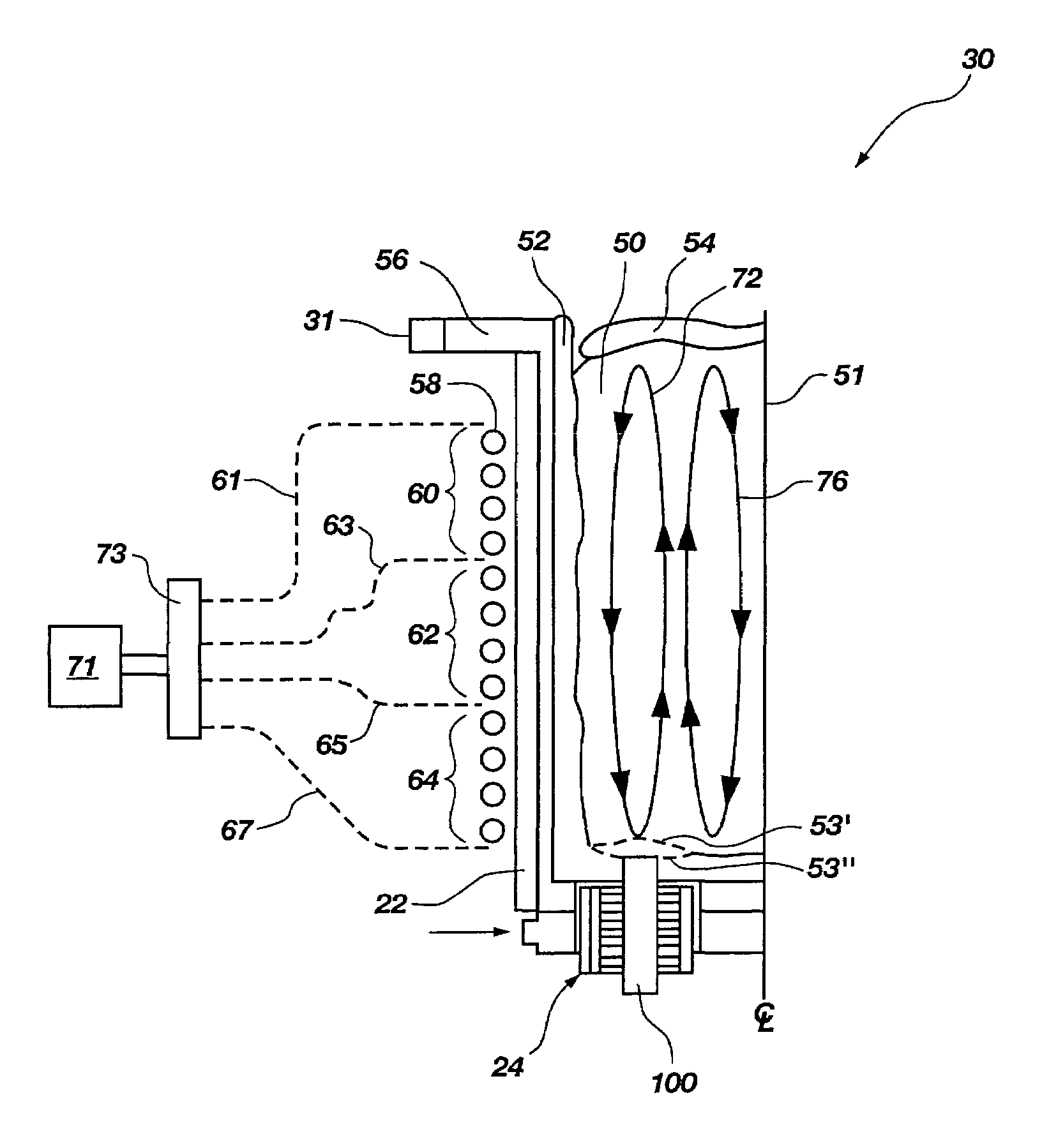
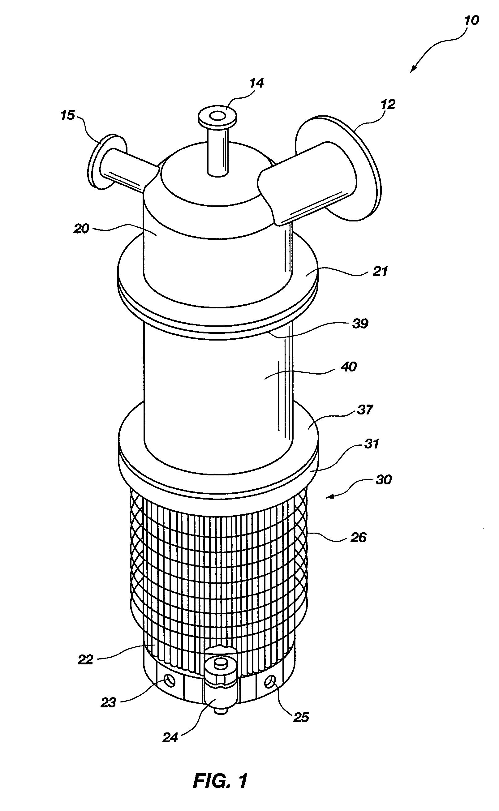
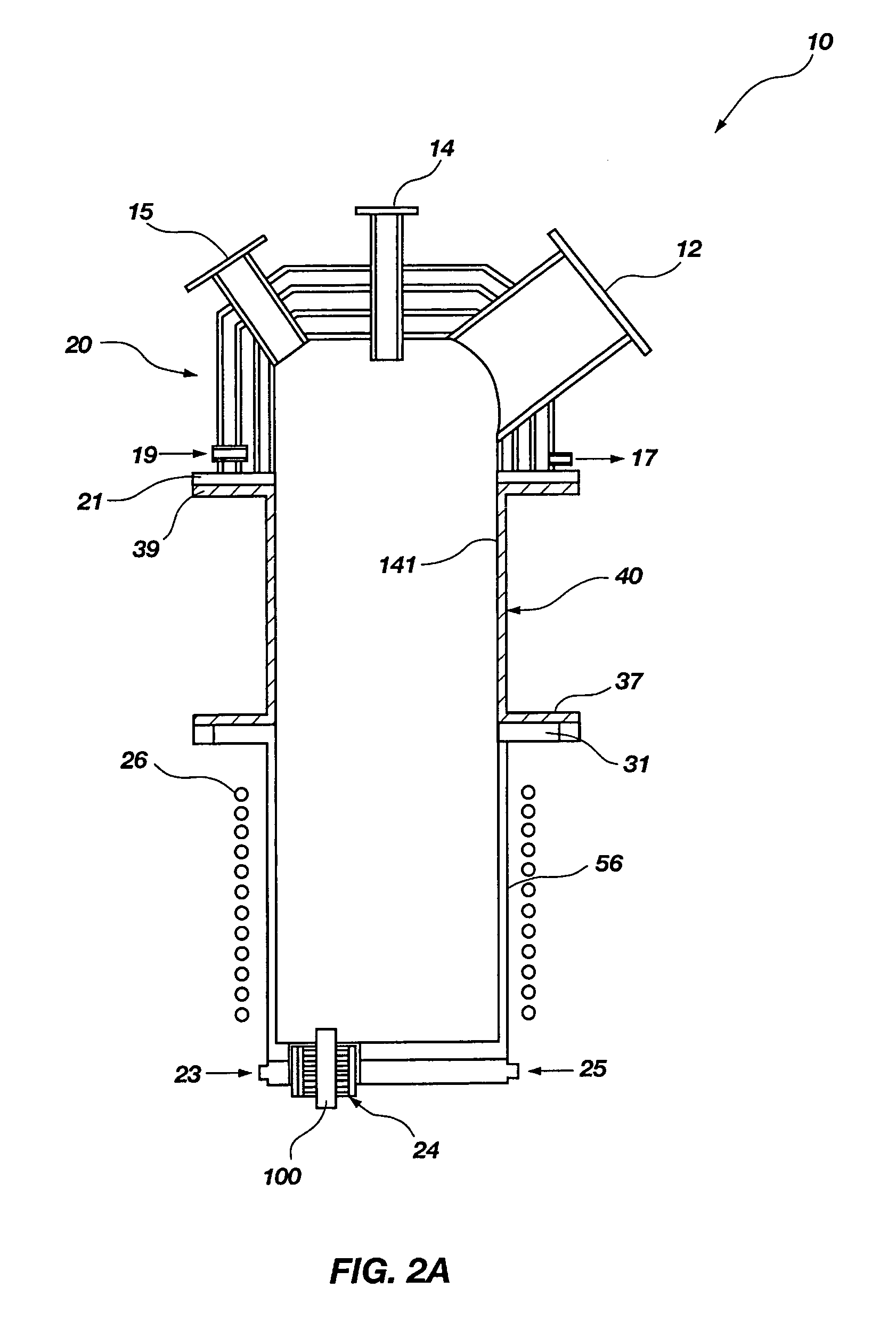
[0033]FIGS. 1 and 2A show a perspective view of an induction melter 10 of the present invention as well as a schematic cross-sectional view thereof, respectively. Generally, cold-crucible-induction melter 10 includes head assembly 20 affixed to disengagement spool 40 by way of mating lower flange 21 and upper flange 39 of head assembly 20 and disengagement spool 40, respectively. Disengagement spool 40 is affixed to furnace body 30 by way of lower flange 37, which is affixed to the upper flange 31 of the furnace body 30. Lid assembly 20 of the present invention includes off-gas port 12 for removing gasses from the cold-crucible-induction melter 10 during operation, feed port 14 for adding waste material to the cold-crucible-induction melter 10, and view port 15 for observing the conditions within the cold-crucible-induction melter 10. Also, head assembly 20 includes inlet port 19 and outlet port 17 for cooling the head assembly 20 by flowing a gas therethrough, as described in more ...


PUM


Abstract

Apparatus and methods of operation are provided for a cold-crucible-induction melter for vitrifying waste wherein a single induction power supply may be used to effect a selected thermal distribution by independently energizing at least two inductors. Also, a bottom drain assembly may be heated by an inductor and may include an electrically resistive heater. The bottom drain assembly may be cooled to solidify molten material passing therethrough to prevent discharge of molten material therefrom. Configurations are provided wherein the induction flux skin depth substantially corresponds with the central longitudinal axis of the crucible. Further, the drain tube may be positioned within the induction flux skin depth in relation to material within the crucible or may be substantially aligned with a direction of flow of molten material within the crucible. An improved head design including four shells forming thermal radiation shields and at least two gas-cooled plenums is also disclosed.

Description

GOVERNMENT RIGHTS[0001]The United States Government has certain rights in this invention pursuant to Contract No. DE-AC07-99ID13727, and Contract No. DE-AC07-05ID14517 between the United States Department of Energy and Battelle Energy Alliance, LLC.FIELD OF THE INVENTION[0002]Field of the Invention: The present invention relates generally to induction melting apparatus for use in processing radiological and hazardous waste. More particularly, embodiments of the present invention relate to induction melting apparatus comprising induction coil assemblies, bottom drain assemblies, high-temperature head assemblies, and methods of control and design therefor.BACKGROUND OF THE INVENTION[0003]Environmental concerns have created a demand for apparatus and methods for treating a variety of waste. For instance, treatment of waste which contains constituents known to damage human health or ecosystems, such as hazardous metals, radioactive materials, hazardous organic compounds, or other hazard...

Claims


Application Information

Patent Timeline
Patent Type & Authority Patents(United States)
IPC IPC(8): F27D23/04H05B6/34F27D27/00F23G5/08F27B14/06F27B14/08F27D99/00H05B6/36
CPCF23G5/085F27B14/063H05B6/367F27B14/0806F27D27/00H05B6/34F27B14/08F23G2202/20F23G2204/204F23G2209/18F23G2209/20F27D99/0006F27D2099/0015Y02P10/25
Inventor ROACH, JAY A.RICHARDSON, JOHN G.RAIVO, BRIAN D.SOELBERG, NICHOLAS R.
Owner BATTELLE ENERGY ALLIANCE LLC
Why Eureka
Try Eureka