Apparatus and method for movement measurement and position tracking of long, non-textured metal objects at an elevated temperature

a metal object, non-textured technology, applied in the direction of testing food, instruments, image enhancement, etc., can solve the problems of significant deviation in accuracy, pattern on “regularly textured” objects cannot provide uniqueness, and vision systems have no unique pattern to track

Inactive Publication Date: 2006-01-31
OG TECH INC
View PDF6 Cites 14 Cited by
  • Summary
  • Abstract
  • Description
  • Claims
  • Application Information

AI Technical Summary

Benefits of technology

[0011]The present invention proposes to utilize the marks created by the formation of scale, item 4 in FIG. 1, (surface oxidation spots on hot metal objects) as the basis for the imaging-based motion measurement and tracking. The scale marks 4 are useful in the present invention because the scale marks are always on the hot metal object surfaces, are typically random, and are typically discernable with a commonly known image processing techniques such as pattern match or geometrical search, either gray-scale based or contour-based.

Problems solved by technology

However, for a long, non-textured (or regularly textured) object, such as a long steel bar or a long steel sheet / strip, vision systems have no unique patterns to track.
The patterns on a “regularly textured” object cannot provide the uniqueness for the purpose of identifying (tracking) the same point on the object.
There are drawbacks in this approach.
The contact head may wear and thus induce significant deviations in accuracy over time.
The contacting device occupies valuable space in the hot metal working equipment.
Installation of the contacting device requires a significant period of down time of the hot metal working equipment.
This approach is not accurate.
There could be very significant accumulated errors in the measurement due to variation in moving speed and feed length.

Method used


Image

  • Apparatus and method for movement measurement and position tracking of long, non-textured metal objects at an elevated temperature
  • Apparatus and method for movement measurement and position tracking of long, non-textured metal objects at an elevated temperature
  • Apparatus and method for movement measurement and position tracking of long, non-textured metal objects at an elevated temperature

Examples


Embodiment Construction

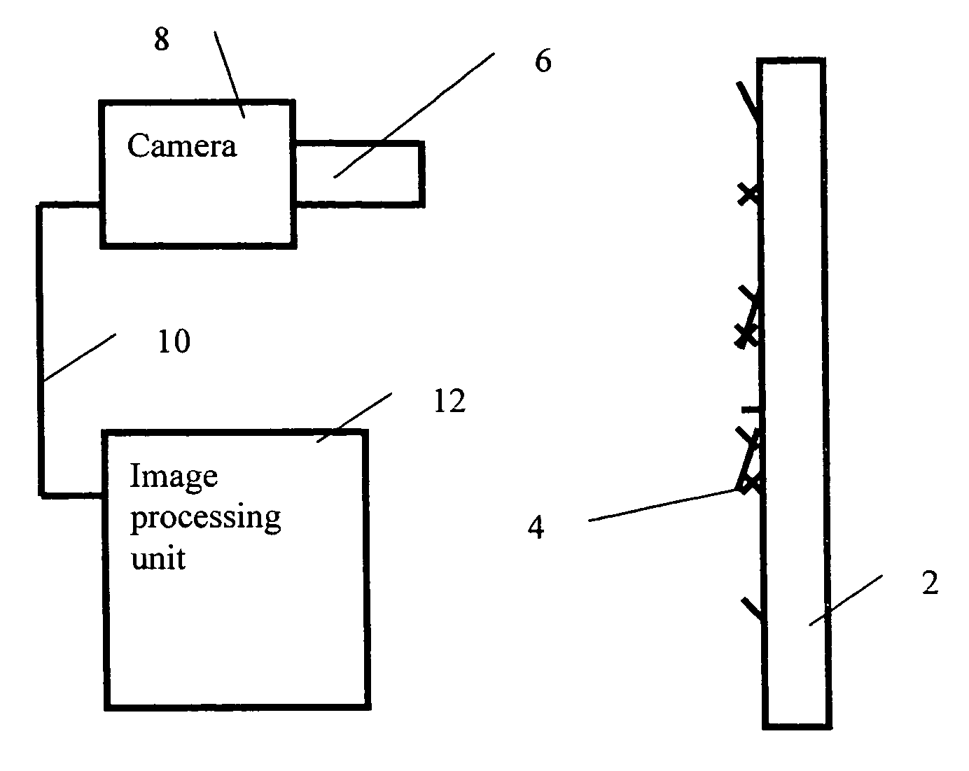
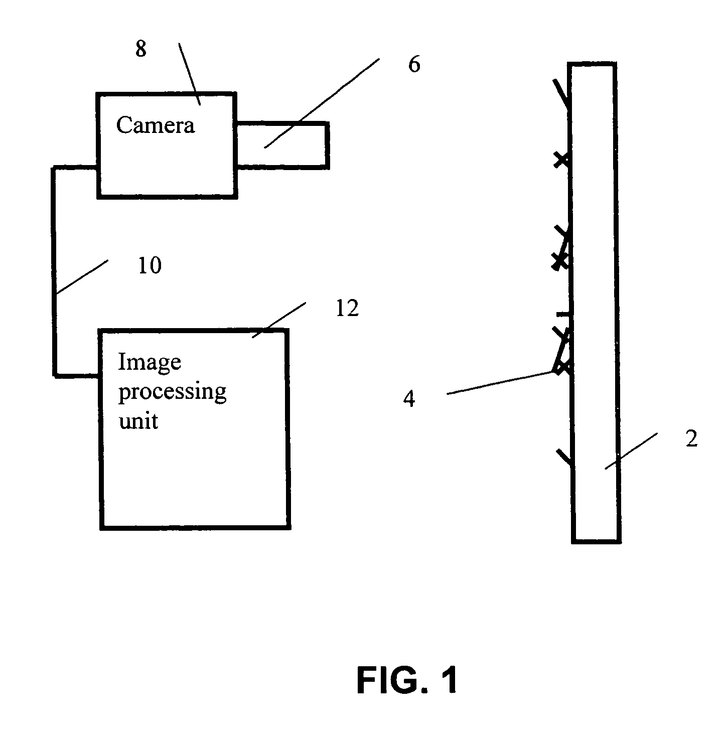
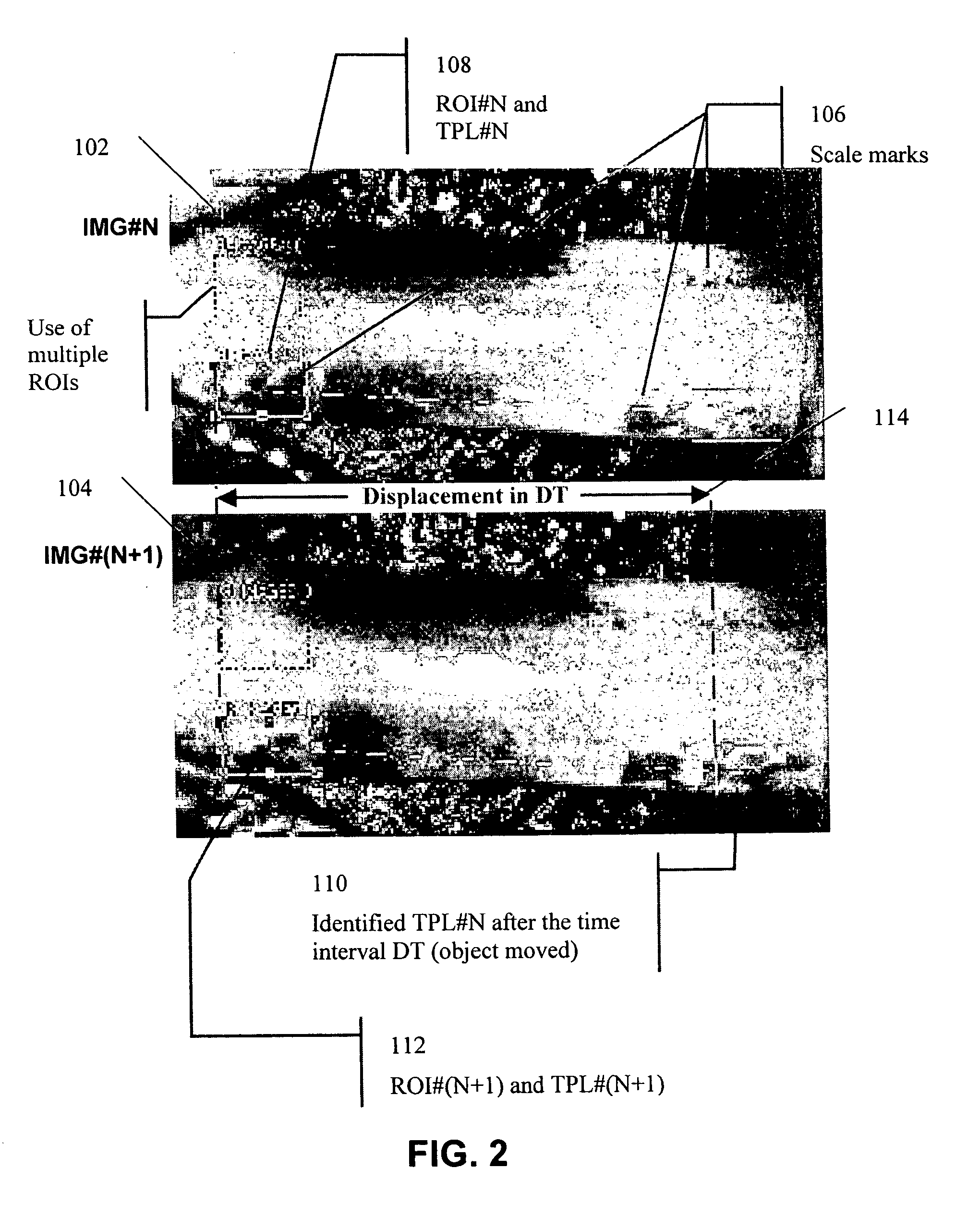
[0031]Referring now to FIG. 1 of the drawings, in one embodiment of the present invention the target or object 2 is a long, non-textured metal piece at an elevated temperature. Oxidation process will occur on the surface of this metal piece as the bulk material of this metal piece interacts with the fluid elements in the environment surrounding the metal piece such as oxygen in the air. Such oxidation process typically will not occur uniformly because of the randomness of the surface microstructure of the metal piece. Therefore, such oxidation process results in irregular, unique surface blobs typically known as scale, item 4 in FIG. 1. The image patterns of scale are as shown in FIG. 2.

[0032]Referring still to FIG. 1, such scale 4 is represented by randomly positioned and oriented short lines. The present invention utilizes the random and unique property of scale 4 to perform non-contact measurement / tracking for the long, non-textured metal piece 2. In order to capture the random a...


PUM


Abstract

A motion detection system, and more particularly, a non-contact, movement-measurement and position-tracking device, and a method of applying the device on long, non-textured or regularly textured metal objects at an elevated temperature are invented. The invention takes advantage of the oxidation marks, also known as scale, on the surface of the metal object to track the motion. The oxidation marks are typically random and irregular, providing a means for pattern tracking using imaging technologies.

Description

RELATED APPLICATIONS[0001]This application claims the benefit of U.S. provisional application Ser. No. 60 / 420,089 filed Oct. 21, 2002, herein incorporated by reference in its entirety.BACKGROUND OF THE INVENTION[0002]1. Technical Field[0003]The present invention relates generally to a motion detection system, and more particularly, to a non-contact, movement-measurement and position-tracking device and to a method of applying the device on long, non-textured or regularly textured metal objects at an elevated temperature.[0004]2. Description of the Related Art[0005]Vision systems have been used to provide non-contact movement measurement and position tracking for small objects, such as a baseball or a pin-pong ball, and for textured long objects, such as a cloth web with printed pattern. In these applications, specific patterns (color or optical geometry) are used to identify the position of the object or the movement (both in quantity and direction) of the object. Such specific patt...

Claims


Application Information

Patent Timeline
Patent Type & Authority Patents(United States)
IPC IPC(8): G01P3/36
CPCG01P3/36G06T7/2033G01P3/68G06T2207/30136G06T7/246
Inventor CHANG, TZYY-SHUH
Owner OG TECH INC
Why Eureka
Try Eureka