Eureka AIR delivers breakthrough ideas for toughest innovation challenges, trusted by R&D personnel around the world.

Location tracking system

Active Publication Date: 2011-09-01
9SOLUTIONS
View PDF8 Cites 142 Cited by
  • Summary
  • Abstract
  • Description
  • Claims
  • Application Information

AI Technical Summary

Problems solved by technology

However, their problem is that they are not suitable for indoor location tracking, because GPS signals do not penetrate building walls.
A problem with such systems is that if high resolution is needed for the tracking, numerous base stations have to be disposed throughout the area where the location tracking is to be carried out.
This leads to high installation and maintenance costs.

Method used


Image

  • Location tracking system
  • Location tracking system
  • Location tracking system

Examples


Embodiment Construction

[0015]The following embodiments are exemplary. Although the specification may refer to “an”, “one”, or “some” embodiment(s) in several locations, this does not necessarily mean that each such reference is to the same embodiment(s), or that the feature only applies to a single embodiment. Single features of different embodiments may also be combined to provide other embodiments.

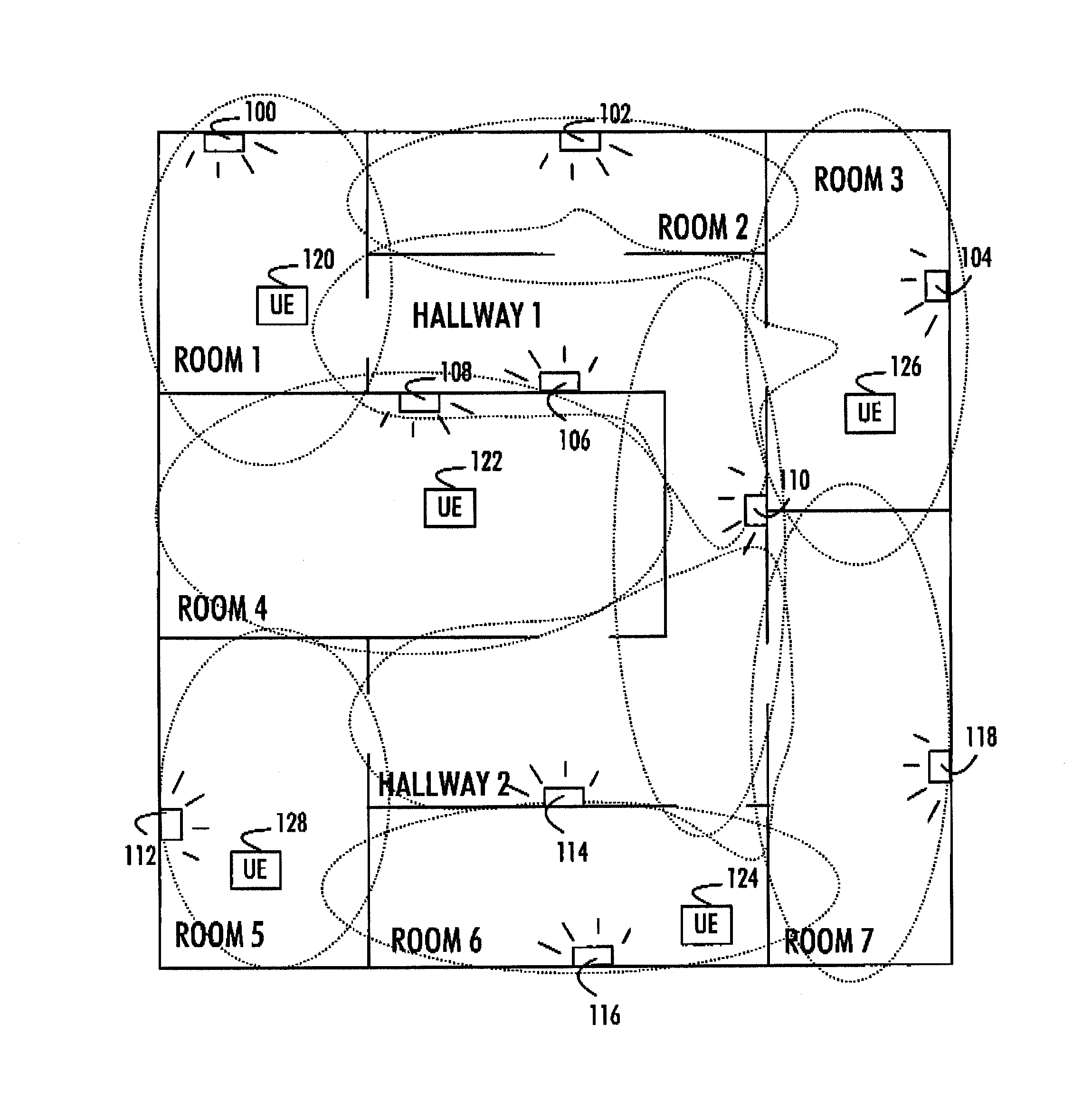
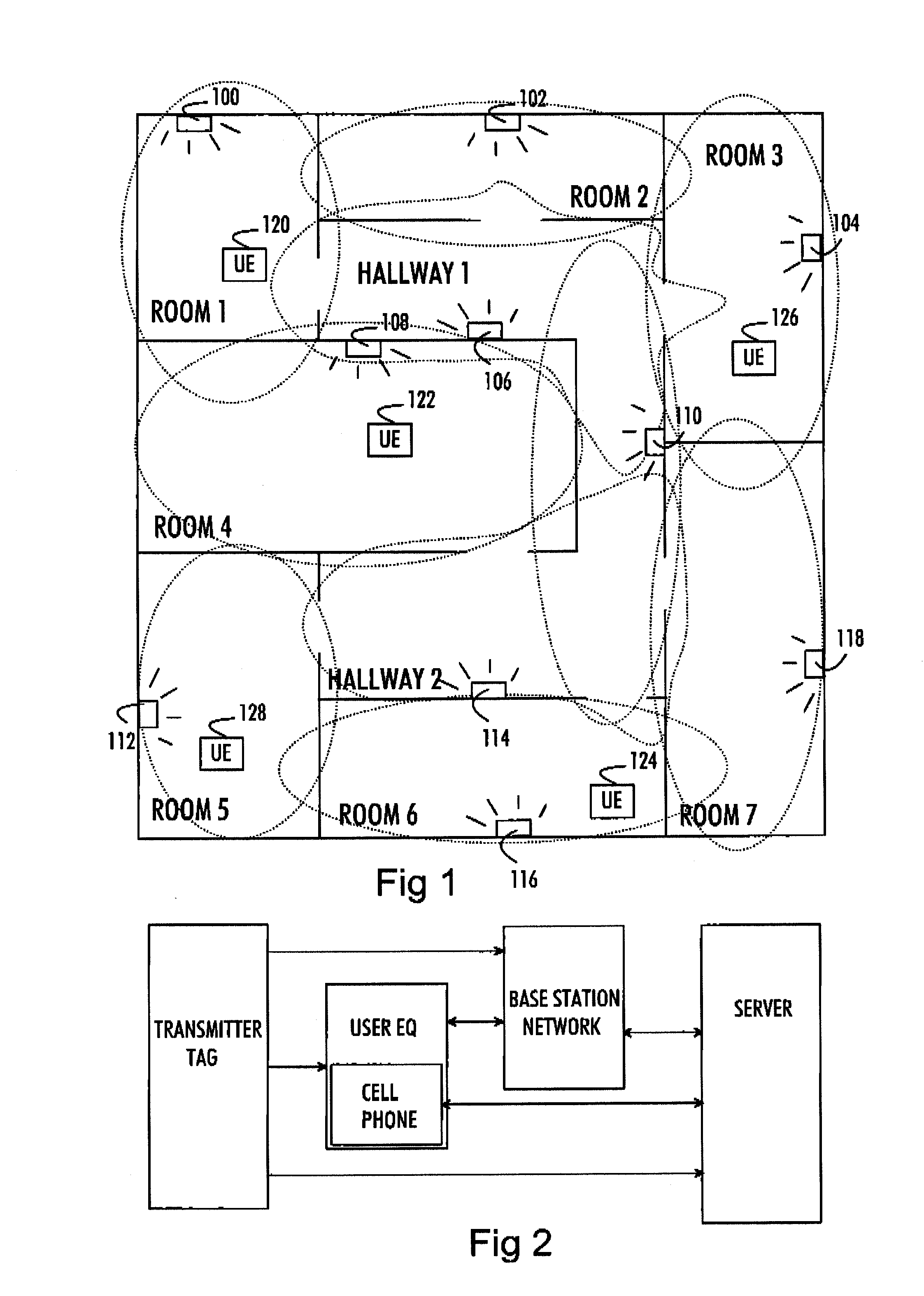
[0016]FIG. 1 illustrates a layout of a building to which embodiments of the invention may be applied. The embodiments are particularly suitable for indoor location tracking, but the invention may equally be utilized in outdoor applications. The layout of FIG. 1 illustrates a number of rooms with doors illustrated by discontinuations in the room walls, and a hallway providing access from one room to another. People inside the building are represented by their user equipment 120, 122, 124, 126, and 128.

[0017]The location tracking is enabled by disposing a plurality of transmitter tags 100 to 118 throughout the b...


PUM


Abstract

This document presents a location tracking system. Transmitter tags are disposed throughout the area where the location tracking is carried out. The transmitter tags are configured to transmit their unique identifiers. A personal radio communication device being tracked detects a unique identifier received from a transmitter tag and transmits the detected unique identifier to a server. The server links a known physical location associated with the unique identifier to an identifier of the personal radio communication device so as to carry out location tracking.

Description

FIELD[0001]The invention relates to the technical field of location tracking systems.BACKGROUND[0002]Prior art teaches several types of location tracking systems. Satellite based tracking systems, e.g. Global Positioning System (GPS), are probably the most common location tracking systems. However, their problem is that they are not suitable for indoor location tracking, because GPS signals do not penetrate building walls. For indoors location tracking, prior art teaches systems that utilize a pico network of wireless base stations, and the location of a given person in the coverage area of the pico network is determined on the basis of which wireless base station currently serves a personal communication device of the person. A problem with such systems is that if high resolution is needed for the tracking, numerous base stations have to be disposed throughout the area where the location tracking is to be carried out. This leads to high installation and maintenance costs.BRIEF DESC...

Claims


Application Information

Patent Timeline
IPC IPC(8): H04W64/00H04W4/029
CPCG01S1/68H04W4/043H04W4/028H04W4/029
Inventor HERRALA, SAMIKYLMANEN, JARISIVONEN, TEEMU
Owner 9SOLUTIONS
Why Eureka
Eureka Blog
Learn More