Plasma torch

a technology of plasma torch and plasma ions, which is applied in the field of plasma torch, can solve the problems of wasting valuable time, requiring analysis to be stopped and the apparatus to be disassembled and cleaned, and shale coming out of solution, so as to reduce the cross-sectional area, reduce the turbulence and pressure changes, and increase the aerosol velocity

Inactive Publication Date: 2006-01-24
AGILENT TECH AUSTRALIA M
View PDF1 Cites 18 Cited by
  • Summary
  • Abstract
  • Description
  • Claims
  • Application Information

AI Technical Summary

Benefits of technology

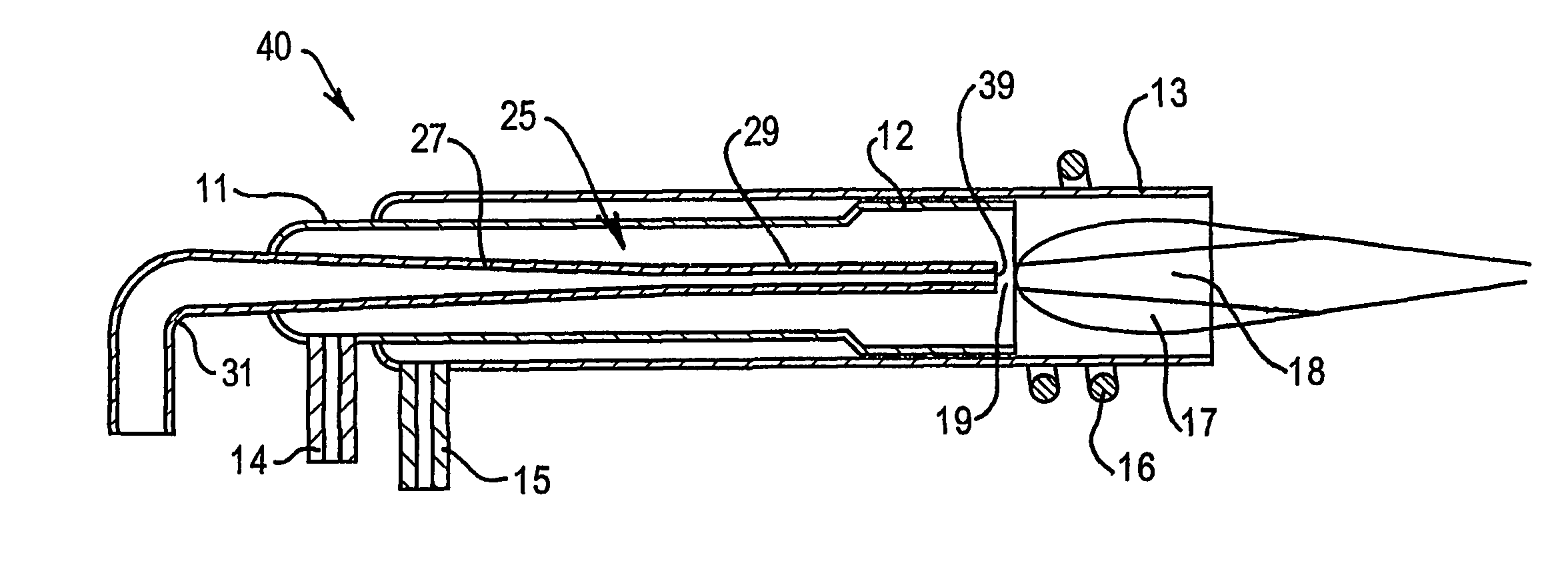
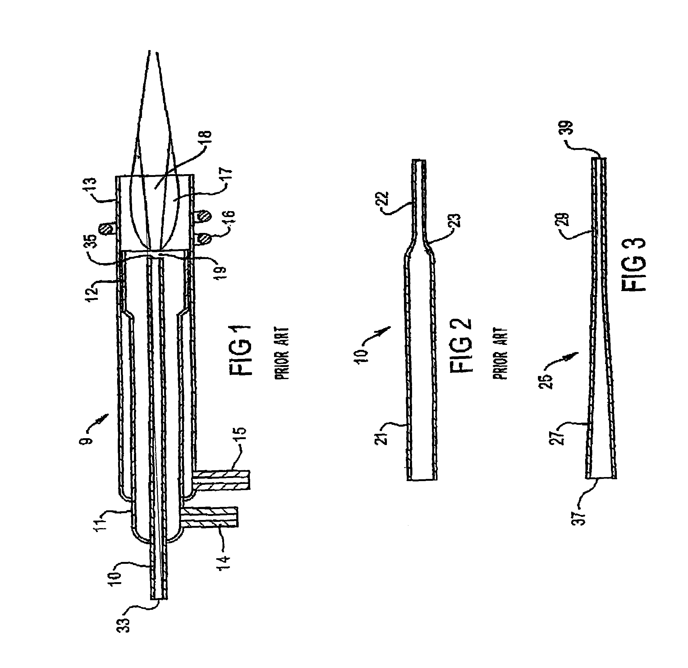
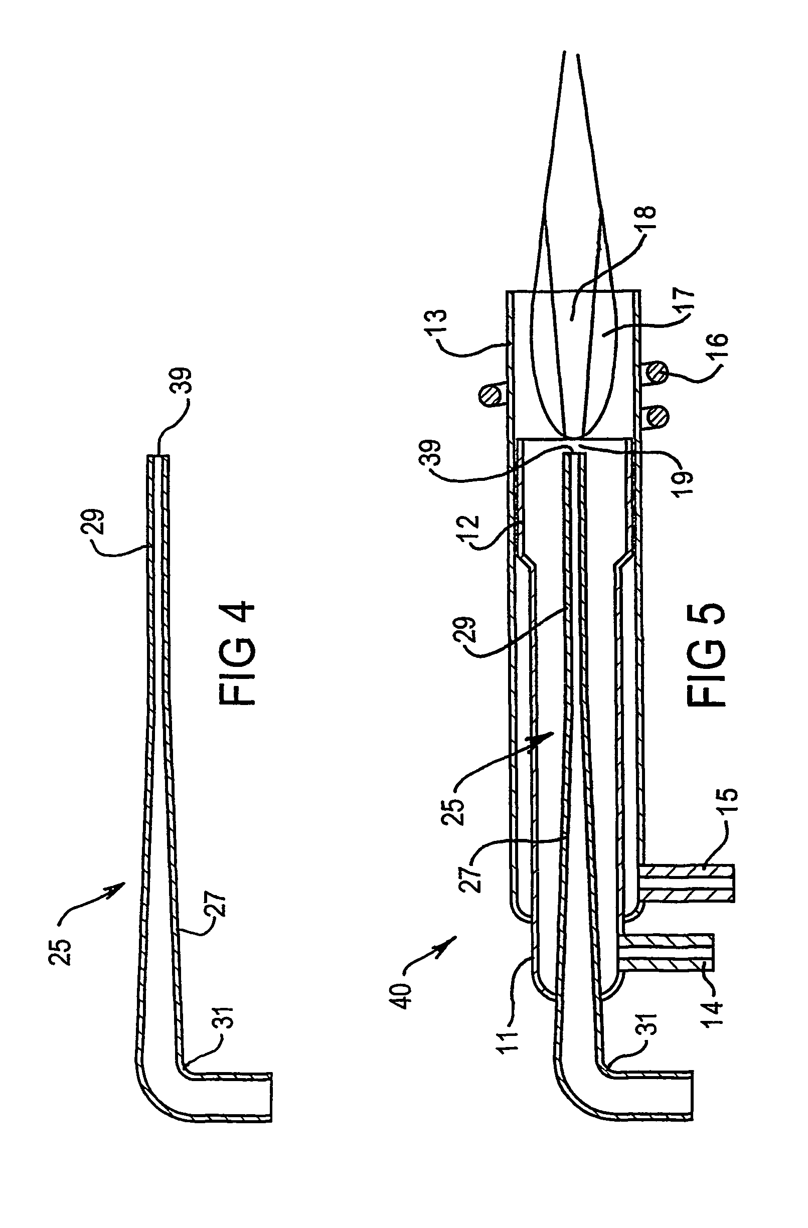
[0006]As the aerosol travels from the inlet of the tube of the torch (typically 4 to 8 mm ID) to the outlet of the tube (typically 0.8–3 mm ID) the velocity of the aerosol increases. This change in velocity (and associated changes in pressure) ought to occur as smoothly as possible, such that turbulence and pressure changes are minimized. The invention meets the stated object by providing a gradual reduction in cross-sectional area between the inlet and the outlet and by providing a smooth transition between the said tapered portion and any parallel portions at each end. The taper may be constant (that is, linear), exponential or of any other shape that can provide an appropriately smooth pathway of decreasing cross-sectional area, blending smoothly into any parallel portions. Such a shape is produced naturally when glass or quartz tube is heated and stretched to produce the taper. If the tube were to be manufactured from ceramic material (either by machining and sintering or moulding), or by shrinking quartz onto a mandrel, care would need to be taken in machining, or in the design and construction of the mould or mandrel, to avoid sharp or abrupt transitions between the tapered portion and any adjacent parallel portions. The length of the tapered portion may be at least five times the internal diameter of the inlet of the tube and is advantageously from five to ten times the internal diameter of the inlet of the tube. Such a design eliminates relatively sudden transitions in the cross sectional area of the tube of the plasma torch, as have been provided in prior art torches, at which salts are preferentially prone to deposit.
[0007]Any turbulence and changes in pressure that may be associated with the transition between a parallel portion of tube at the outlet end and the said tapered portion should occur at a location sufficiently remote from the plasma to be largely unaffected by the heat radiated from the plasma or conducted down the tube from the plasma. This can be achieved in the invention by ensuring that the final change in internal diameter occurs at a distance of 40 to 50 mm from the outlet end of the tube. The known relatively sudden transition in cross-sectional area of a tube in a prior art torch is typically located near the outlet end of the tube and is thus nearby the heat of the plasma. The invention reduces the influence of this factor given the tapered portion provides a gradual and smooth transition between the inlet and outlet cross sections and also that it may be located as remotely as possible from the heat of the plasma, for example, the tapered portion may commence at the inlet.

Problems solved by technology

Attempts to analyse highly concentrated samples can result in salts coming out of solution as the nebulised aerosol is generated and as it is transported through the torch.
Salt particles are often deposited in the nebulizer or in the torch, ultimately causing blockages that require the analysis to be stopped and the apparatus to be disassembled and cleaned.
This wastes valuable time.
Nebulisers that are resistant to obstruction by salts are known in the art, but obstruction of the plasma torch has continued to cause difficulty.

Method used


Image

  • Plasma torch
  • Plasma torch
  • Plasma torch

Examples


Embodiment Construction

[0016]A typical inductively coupled plasma torch 9 is shown in FIG. 1. It consists of three concentric tubes, 10, 11 and 13, usually made out of fused quartz. FIG. 1 shows a torch 9 in which the three tubes are permanently fused together, but it is known in the art to provide a mechanical arrangement whereby the three tubes 10, 11 and 13 are held in their required positions and wherein one or more of the tubes 10, 11 and 13 can be removed and replaced. Such an arrangement is called a demountable torch.

[0017]Tube 13 is the outermost of the three tubes. Tube 11 is the intermediate tube and may be provided with a portion 12 of larger diameter, which may in some designs extend over the entire length of tube 11. The purpose of portion 12 is to provide a narrow annular gap between tubes 11 and 13 for the passage of a plasma forming gas (typically argon) that is supplied though a gas inlet 15. The narrow gap imparts a desirably high velocity to the gas. Radiofrequency induction coil 16 is ...


PUM


Abstract

A torch for producing an inductively coupled or microwave induced plasma for use in spectrochemical analysis. The torch includes a central tube (25) for conveying a flow of a gas carrying sample aerosol to a plasma (17) produced in the torch. The tube (25) has an inlet (31) and an outlet (39) of smaller size than the inlet and is shaped to deliver a substantially laminar flow of the gas at the outlet (39). The tube (25) is tapered along at least a substantial portion of its length such that its cross-section area gradually and smoothly reduces towards its outlet (39) along at least a substantial portion of its length. It has been found that such a tapered tube is resistant to obstruction by salts deposited from samples containing high levels of dissolved solids.

Description

TECHNICAL FIELD[0001]This invention relates to a plasma torch for spectrochemical analysis, for example for producing an inductively coupled plasma or a microwave induced plasma.BACKGROUND OF THE INVENTION[0002]A common requirement in spectrochemical analysis with inductively coupled or microwave induced plasma torches is to analyse liquid samples having relatively high concentrations of dissolved solids. In extreme cases the concentrations of such samples might approach the saturation point of one of the dissolved components. Liquid samples are usually introduced a plasma torch as aerosols produced by a nebulizer. Attempts to analyse highly concentrated samples can result in salts coming out of solution as the nebulised aerosol is generated and as it is transported through the torch. Salt particles are often deposited in the nebulizer or in the torch, ultimately causing blockages that require the analysis to be stopped and the apparatus to be disassembled and cleaned. This wastes v...

Claims


Application Information

Patent Timeline
IPC IPC(8): G01N21/73G01N27/62G01N21/68H05H1/30
CPCG01N21/73H05H1/30H01J49/105
Inventor WISEMAN, ALAN G.
Owner AGILENT TECH AUSTRALIA M
Why Eureka
Try Eureka