
Cooling system and method to cool a gantry

a cooling system and gantry technology, applied in tomography, material analysis using wave/particle radiation, instruments, etc., can solve the problems of complex and problematic dissipation of heat accumulating in the operation of the x-ray system, 99% of electrical energy used, and the x-ray source is transduced into heat energy, etc., to achieve simple and cost-effective systems, reduce maintenance costs of the entire system, and reduce production costs

Active Publication Date: 2006-01-24
SIEMENS HEATHCARE GMBH
View PDF6 Cites 35 Cited by
  • Summary
  • Abstract
  • Description
  • Claims
  • Application Information

AI Technical Summary

Benefits of technology

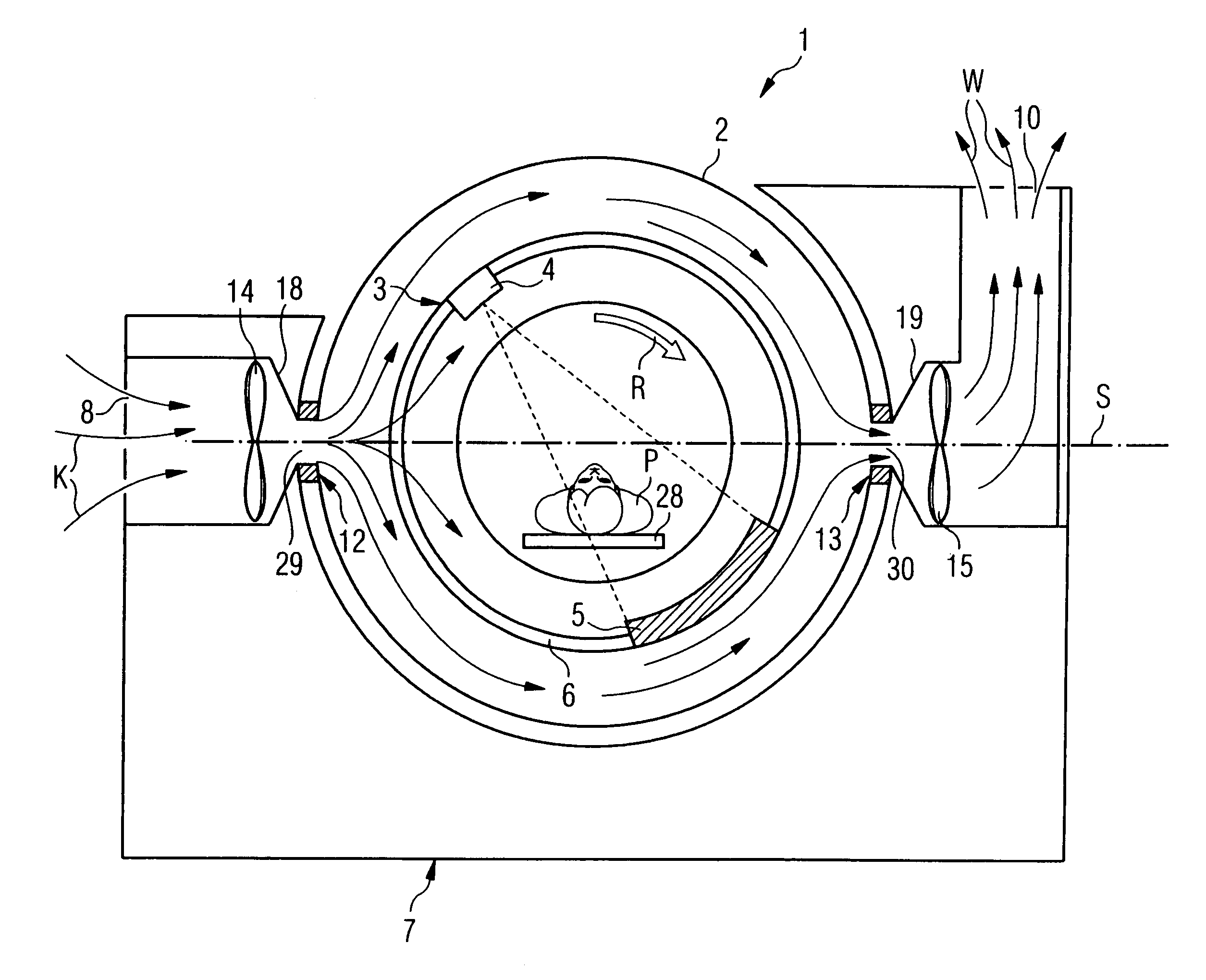
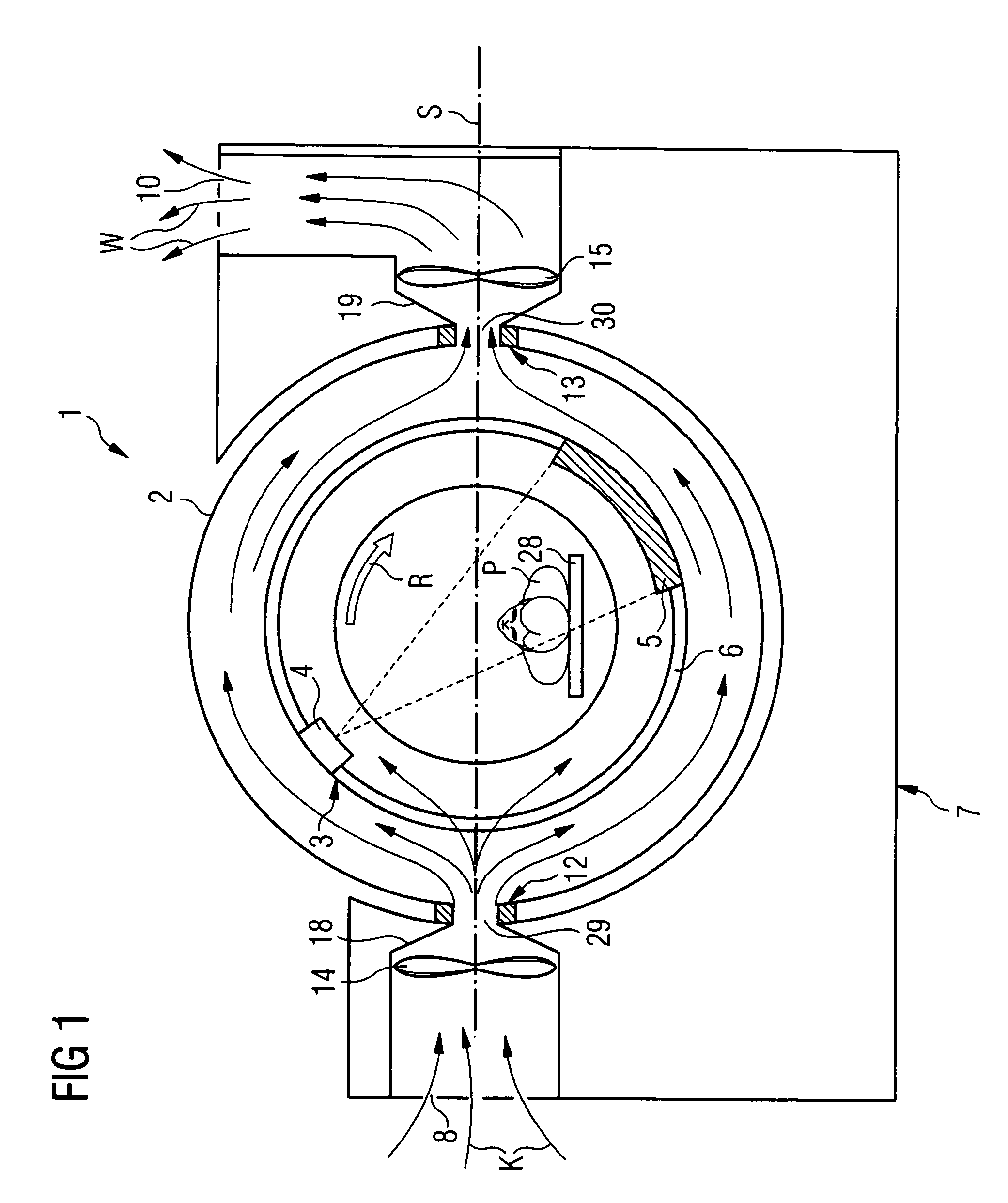
[0010]The inventive cooling system has the advantage that neither heat sinks that absorb and dissipate the waste heat of the components of the gantry, in particular of the x-ray source, from the gantry housing must necessarily be integrated into the gantry housing, nor that idle period or pauses of the gantry are necessary to dissipate the heat, since a cooling gas continuously flows from the gantry foot through the gantry housing and from the gantry housing back into the gantry foot, and this flow efficiently cools the components including the x-ray source which are located in the gantry housing.
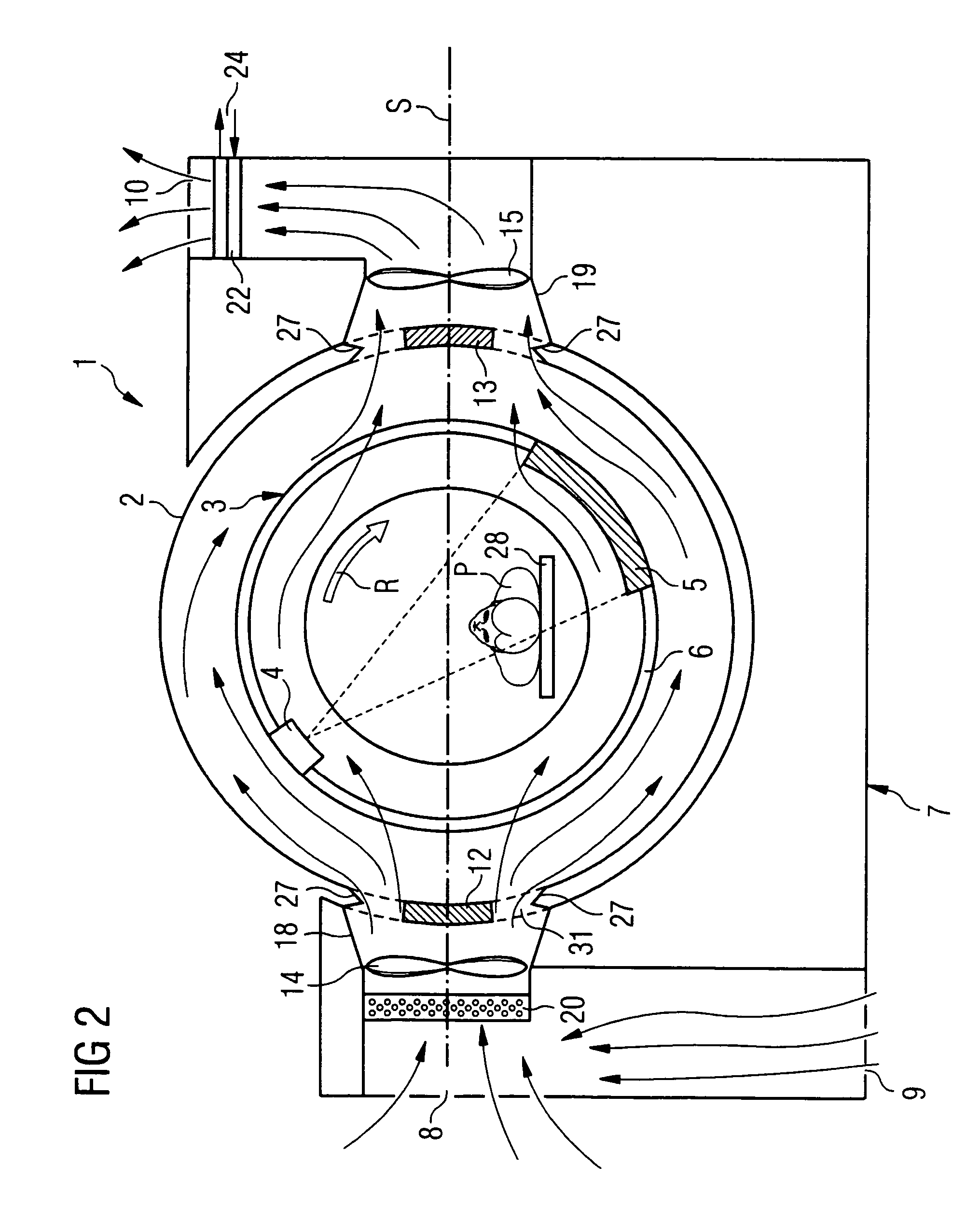
[0015]In a further open embodiment or variant of the invention, the gantry housing is designed so that the outer wall of the gantry housing itself comprises at least one exhaust opening. In this variant, the cooling gas is also directed out from the gantry foot in a bearing region in the gantry housing. However, the cooling gas here escapes directly from the exhaust opening of the gantry housing without first being directed back into the gantry foot. The exhaust openings can be one or more large openings. However, the housing is preferably perforated radially outwards in a specific region, that extends away from the examination subject. The cooling system in this embodiment is preferably fashioned so that the air flows into the gantry housing in the region of both pivot bearings. The cooling gas throughput is thereby increased.
[0022]In order increase the effect of the cooling system, in the preferred exemplary embodiments of the invention additional heat exchangers are mounted in the stationary part. The heat exchangers cool the air, for example, before the entry into the gantry housing and / or after leaving the gantry housing before the discharge into the patient examination space, or in a closed circuit before a renewed flow-through from the gantry housing into the gantry foot. In an exemplary embodiment, the heat exchangers are preferably placed adjacent to the blowers. The heat exchangers can be connected to a cooling fluid, such as, for example, a simple cooling water.
[0025]The substantial advantage of the fashioning of the cooling system as a cooling gas supply system in the region of the bearings is that it is not necessary to install a plurality of heat exchangers in the gantry housing. The cooling system is thus a relatively simple and cost-effective system. Since no additional mechanical parts must be installed inside the gantry housing, on the one hand the production costs are already lower and, on the other hand, the maintenance costs of the entire system are reduced. Moreover, the cooling system also has the advantage that a cost-saving design of a smaller gantry housing is possible. An additional advantage of this cooling system is that the coupling of an external coolant pump to the outside of the gantry housing during the idle period pauses is not necessary. The pivotable realization of the gantry housing is thus simplified.
[0026]The inventive cooling system can be used in special designs, and also with particular advantage in a continuously rotating computer tomography device. Thus, the cooling system can be used in a computer tomography device which, for example, rotates uninterrupted during a working shift, during a workday or over a plurality of examinations. Given such an embodiment, the rotation of the scanning unit around the system axis can be effected uninterrupted from the beginning of the examination of a first examination subject until the end of a following examination of a second examination subject. “Uninterrupted” does not necessarily mean that the uninterrupted rotation is effected with constant rotation frequency. Rather, the rotation frequency of the scanning unit can advantageously be set differently dependent on the type of the desired examination, for example for an examination of the heart or of the abdomen of a patient. A correspondingly fashioned computer tomography device can in particular be fashioned so that the scanning unit then rotates with a preset rotation speed (“stand-by setting”) in the event that no examination is directly occurring. This rotation speed is, for example, less than the rotation speeds available for the applications, or is in the range of the average value of the rotation speeds available for the applications, so that the change of the rotation speed is small given a new application in the middle of other applications. The span of time of the uninterrupted rotation can also extend over a week or longer. A continuously rotating computer tomography device has the advantage that time-intensive braking or starting intervals can be avoided, which up until now were necessary, for example for an always-necessary repositioning of the scanning unit before each new examination. Given a continuously rotating computer tomography device, the temperature stability and temperature homogeneity of the entire tomography device is additionally improved. This stability enables an execution of the cooling system in a simplified manner.
[0027]Moreover, the cooling system can also be used supplementary to already known cooling methods. The inventive air cooling can preferably also be used in order to cool the heat exchangers arranged on and rotating with the gantry, and thus to increase their efficiency.

Problems solved by technology

A basic problem in all x-ray systems is that 99% of the electrical energy used in the generation of the x-ray radiation in the x-ray source is transduced into heat energy.
Due to this continuous rotation movement, the extremely high temperatures and the narrowness of the inner space of the gantry housing, the dissipation of the heat accumulating in the operation of the x-ray system proves to be complicated and problematic.
It proves to be disadvantageous in the cited cooling systems that a plurality of precise mechanical and electrical components are necessary that, due to their function, tend to wear out and must be correspondingly maintained.
A further disadvantage is that the gantry housing must be correspondingly, voluminously dimensioned, due to the size of the required heat exchanger.
However, it has a what is disadvantage which is that the cooling of the coolant is possible only given sufficient idle periods.
Moreover, the pivotable realization of the gantry housing is hampered due to the necessary coupling to an external coolant circuit.

Method used


Image

  • Cooling system and method to cool a gantry
  • Cooling system and method to cool a gantry
  • Cooling system and method to cool a gantry

Examples


Embodiment Construction

[0034]The principles of the present invention are particularly useful when incorporated in the cooling system illustrated in FIGS. 1–4.

[0035]The computer tomography system 1 shown in FIG. 1 comprises as a primary component a stationary part 7, which is called a gantry foot in the following and a gantry housing 2, movably positioned thereon, which is fashioned in an approximate torus shape, meaning as a “donut” and is movably mounted on the gantry foot 7. Located in the gantry housing 2 is a gantry 3 with a carrier ring 6, which is also called a drum. The gantry is mounted so that it can be rotated in the rotation direction of arrow R, and an x-ray source 4 and a detector 5 are arranged opposite one another on the gantry 7. In the operation of the computer tomograph 1, the drum 6 rotates around an examination subject or patient P positioned on a bed 28 in the examination space, so that a fan-shaped x-ray beam emitted by the x-ray source 4 penetrates the examination subject and imping...


PUM


Abstract

A cooling system for a gantry of a computer tomography system which has a gantry supporting an x-ray source being positioned in a gantry housing and being rotatable around a rotation axis, the gantry housing being positioned by at least one bearing on a stationary part of the computer housing so that it can be moved relative to the housing. The cooling system comprises a cooling gas supply arrangement or device directing a cooling gas flow in the region of at least one bearing between the stationary part and the gantry housing.

Description

BACKGROUND OF THE INVENTION[0001]The invention concerns a cooling system for a gantry and a computer tomography system with an x-ray source, positioned in a gantry housing and rotatable around a rotation axis, in which the gantry housing is positioned at a stationary part of the computer tomography system so that it can be moved, in particular pivoted, by means of at least one bearing. Moreover, the invention concerns a corresponding method to cool such a gantry.[0002]In computer tomography systems, three-dimensional slice images of the inside of an examination subject are generated with the aid of an x-ray method. For this, by means of a scanning unit—in general called a gantry—which comprises an x-ray source normally rotating around the acquisition subject and an image acquisition system, two-dimensional x-ray slice images are generated from which a three-dimensional slice image is reconstructed. The gantry is typically located in a gantry housing which is annularly arranged aroun...

Claims


Application Information

Patent Timeline
IPC IPC(8): H01J35/10A61B6/03G01N23/00G01N23/06H01J35/02H01J35/12H05G1/00H05G1/02
CPCA61B6/4488A61B6/035A61B6/4423G01T1/2985
Inventor MUELLER, HANS-JUERGEN
Owner SIEMENS HEATHCARE GMBH
Learn More