
Method of manufacturing large capacity preforms by MCVD

a technology of mcvd and preforms, which is applied in the direction of glass making apparatus, manufacturing tools, instruments, etc., can solve the problems of increasing the requirements for the purity of the substrate tube material, the deposition rate of mcvd is limited, and the layer can be very thin, so as to achieve the effect of large capacity and less expensiv

Inactive Publication Date: 2006-01-24
DRAKA COMTEQ BV
View PDF7 Cites 12 Cited by
  • Summary
  • Abstract
  • Description
  • Claims
  • Application Information

AI Technical Summary

Benefits of technology

The invention provides a method for manufacturing optical fibers using a substrate tube that is compatible with natural silica and reduces the presence of OH groups that cause undesirable attenuation. The method involves doping the substrate tube with chlorine and fluorine to achieve a refractive index that is lower than that of pure silica. The resulting preform has a small ratio b:a, meaning it has a high purity and is not sensitive to microbending losses. The refractive index of the substrate tube is reduced by the chlorine doping and increased by the fluorine doping to match the refractive index of natural silica. The use of natural silica for building out the substrate tube reduces the cost of manufacturing preforms but may result in a small index step between the substrate tube and the outer cladding. This problem is solved by simultaneously doping the substrate tube with chlorine and fluorine to account for the concentration of OH groups and the softening temperature during fiber drawing. The resulting optical fibers have a small ratio b:a and are not sensitive to microbending losses.

Problems solved by technology

Unfortunately, when the core is close to the substrate tube, purity requirements for the substrate tube material becomes increasingly strict.
However this layer can be very thin if a high purity substrate tube is used.
The deposition rate of MCVD is limited by the transfer of heat through the substrate tube.
That technique suffers from the drawback of the very high cost of synthetic silica jackets.

Method used


Image

  • Method of manufacturing large capacity preforms by MCVD
  • Method of manufacturing large capacity preforms by MCVD

Examples


Embodiment Construction

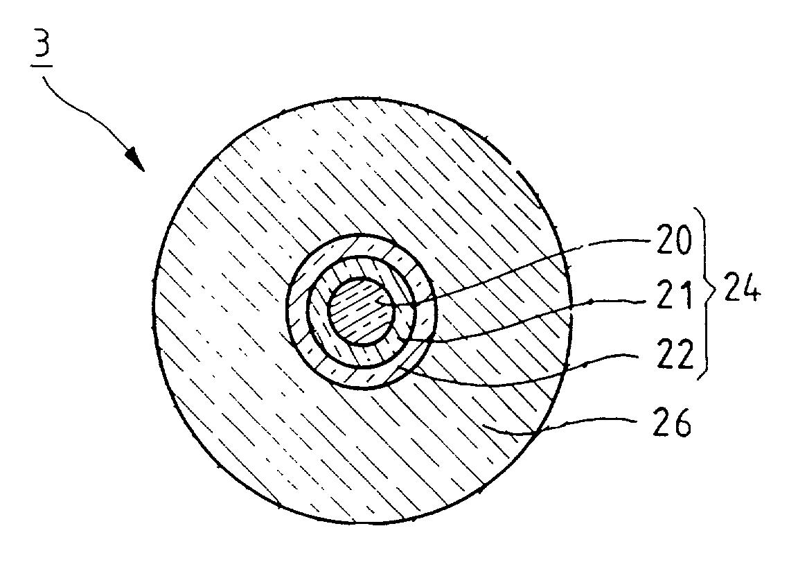
[0037]A primary preform 24 shown in FIG. 1 is made, for example, using the MCVD method by depositing inner layers based on optionally-doped silica to form an optical core 20 and inner cladding 21 inside a substrate tube 22. In order to manufacture the preform, a substrate tube 22 is used that is made of chlorine-doped silica in order to reduce the presence of OH groups, and that is also doped with fluorine at an equivalent concentration. The mass concentration of fluorine preferably satisfies the following relationship: 0.25*XCl<XF<4*XCl.

[0038]It has been found that the presence of fluorine influences the refractive index of the fiber by two distinct mechanisms. The first mechanism whereby fluorine doping reduces refractive index is purely physical and is associated with the material being modified. The interaction between light and the doped material is modified. This property is made use of when it is desired to obtain a low index, e.g. for fibers having depressed-index inner clad...


PUM

PropertyMeasurementUnit
diameteraaaaaaaaaa
temperatureaaaaaaaaaa
concentrationaaaaaaaaaa

Abstract

The invention provides a low cost method of manufacturing high capacity preforms by chemical vapor deposition. More particularly, there is described a method of manufacturing an optical fiber preform, which method comprises the steps of providing a substrate tube of silica doped with sufficient chlorine to obtain an OH concentration of less than 100 ppb and doped with sufficient fluorine proportional to the chlorine doping to obtain a refractive index that is lower than that of a natural silica, depositing inner cladding and an optical core inside the substrate tube, collapsing the substrate tube to form a primary preform, and depositing outer cladding of said natural silica on the resulting primary preform. The invention is applicable to manufacturing optical fibers.

Description

[0001]The invention relates to a method of manufacturing large capacity optical fiber preforms using modified chemical vapor deposition (MCVD) methods.BACKGROUND OF THE INVENTION[0002]The optical fiber is obtained by proportional hot drawing (fiber drawing), i.e. drawing while maintaining the various different portions of the preform.[0003]Preforms can be obtained by CVD methods such as MCVD or by the vapor axial deposition (VAD) method.[0004]When depositing by MCVD, successive layers of oxide compounds are deposited inside a silica tube referred to as a substrate tube, and they are then vitrified by means of a torch. These layers correspond to the core and to the inner portion of the cladding of the preform. They present a refractive index that varies in compliance with the properties that are desired for the optical fiber.[0005]It is desirable for reasons of keeping down method costs to obtain preforms that are of large capacity. It is also desirable to have optical fibers that ar...

Claims


Application Information

Patent Timeline
Patent Type & Authority Patents(United States)
IPC IPC(8): C03B37/018C03C13/04C03B37/012
CPCC03B37/01205C03B37/01291C03B37/01892C03B2201/20C03B2201/075C03B2201/12
Inventor ORCEL, GERARDNICOLARDOT, MARCCAMPION, JEAN-FLORENT
Owner DRAKA COMTEQ BV
Learn More