
Injection control system of internal combustion engine

a technology of injection control system and internal combustion engine, which is applied in the direction of electric control, braking system, instruments, etc., can solve the problem of taking a long time to obtain the desired correction valu

Active Publication Date: 2006-01-17
DENSO CORP
View PDF9 Cites 29 Cited by
  • Summary
  • Abstract
  • Description
  • Claims
  • Application Information

AI Technical Summary

Benefits of technology

[0012]It is therefore an object of the present invention to provide an injection control system of an internal combustion engine capable of shortening a period to complete a correction and of preventing noise generation and emission deterioration, which will be caused if an excessive quantity of fuel is injected in an injection quantity learning operation.
[0014]When an actual injection quantity is very small, there is a possibility that the injection quantity remains zero even if the injection quantity is corrected and renewed. In such a case, it takes a long time to obtain a desired correction value. In contrast, according to the present invention, the calculating means sets at least one of the modification value and the modification speed to a greater value in the case where the command injection quantity is increased in the correction than in the case where the command injection quantity is decreased in the correction. Therefore, the period for converging the correction value can be shortened.

Problems solved by technology

In such a case, it takes a long time to obtain a desired correction value.

Method used


Image

  • Injection control system of internal combustion engine
  • Injection control system of internal combustion engine
  • Injection control system of internal combustion engine

Examples


first embodiment

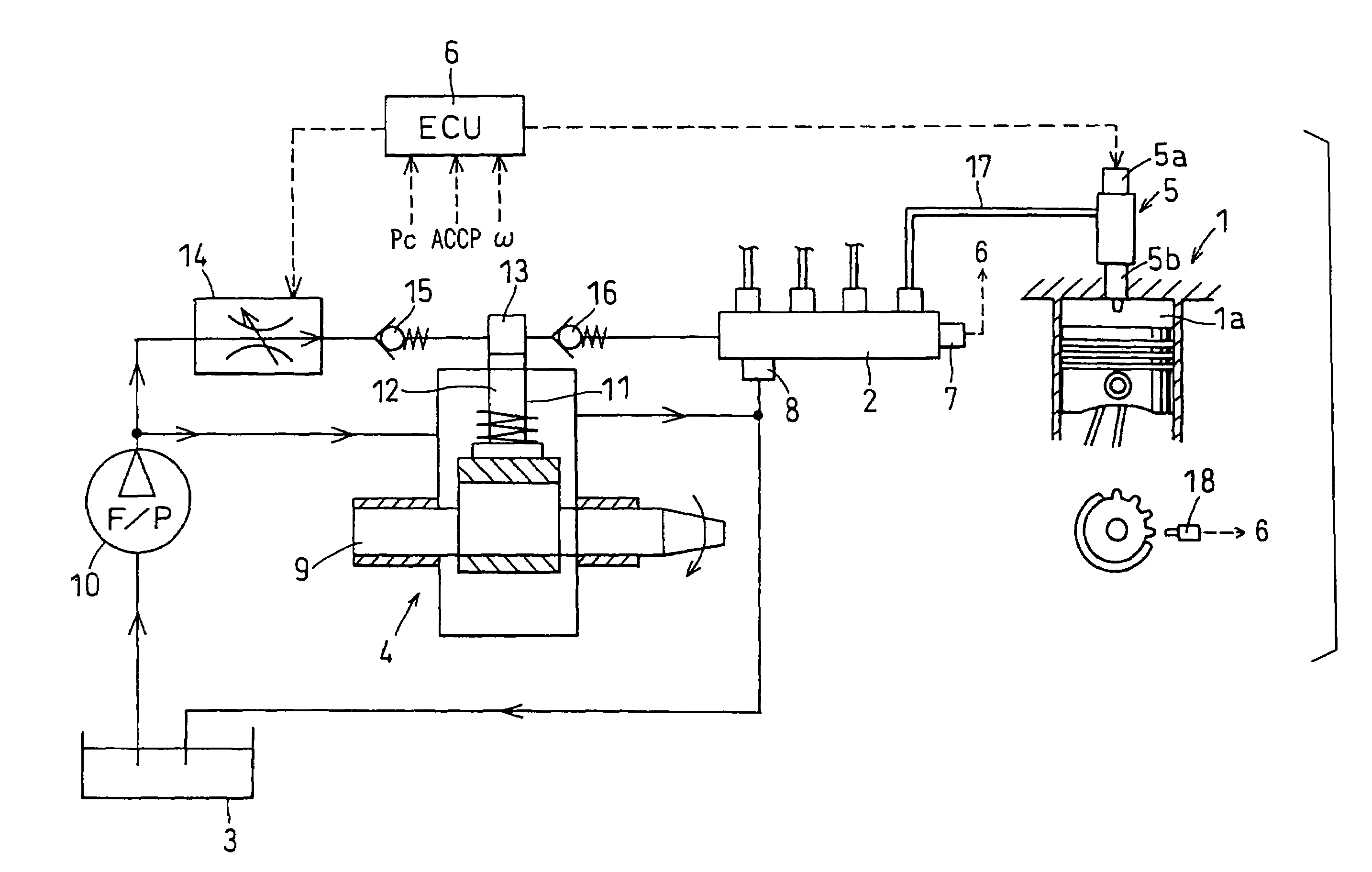
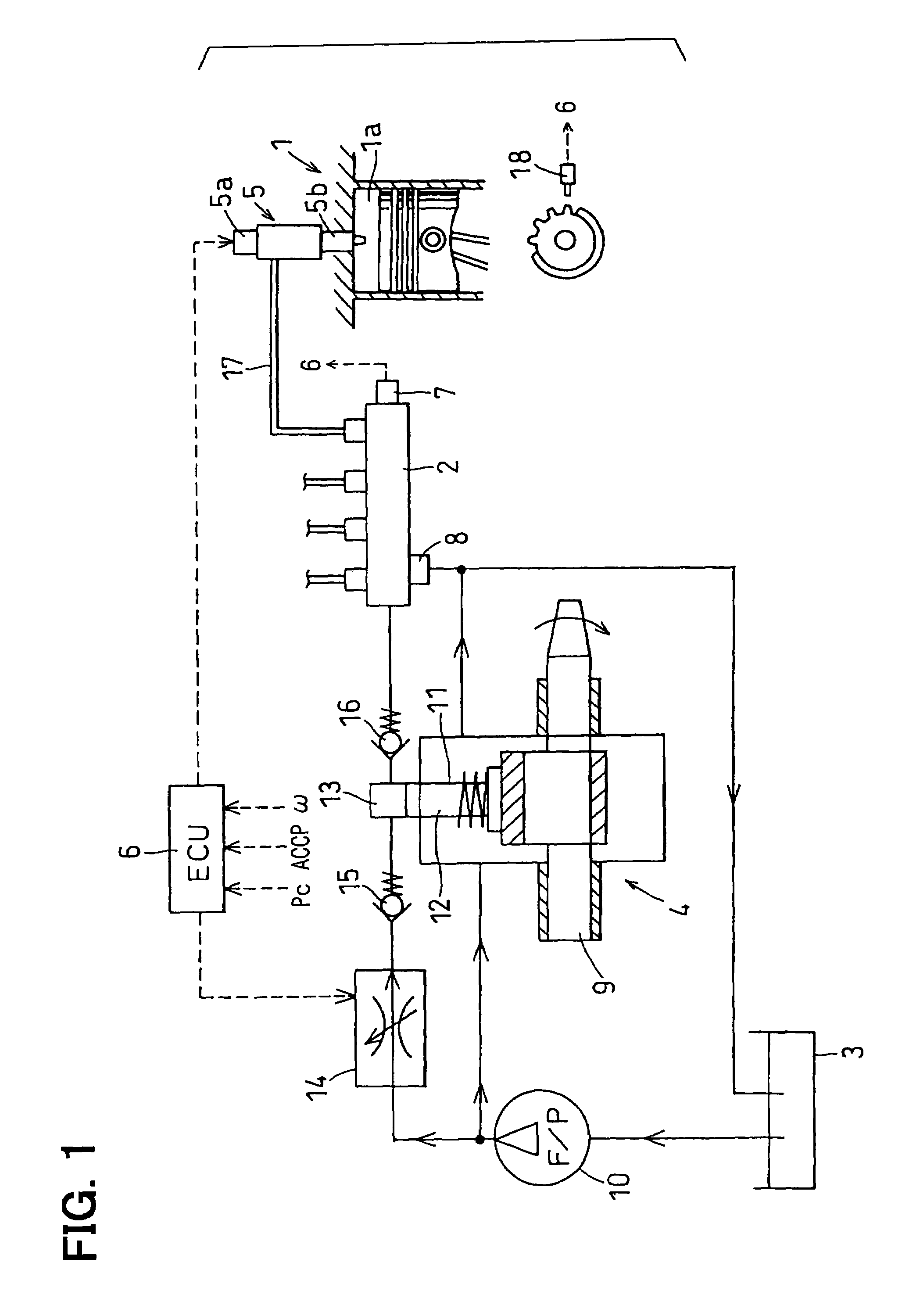
[0025]Referring to FIG. 1, an injection control system of a four-cylinder diesel engine 1 according to a first embodiment of the present invention is illustrated. As shown in FIG. 1, the engine 1 of the present embodiment includes an accumulation type fuel injection system.

[0026]As shown in FIG. 1, the fuel injection system includes a common rail 2, a fuel pump 4, injectors 5 and an electronic control unit (ECU) 6. The common rail 2 accumulates high-pressure fuel. The fuel pump 4 pressurizes fuel drawn from a fuel tank 3 and pressure-feeds the fuel to the common rail 2. The injectors 5 inject the high-pressure fuel, which is supplied from the common rail 2, into cylinders (combustion chambers 1a) of the engine 1. The ECU 6 electronically controls the system.

[0027]The ECU 6 sets a target value of a rail pressure Pc of the common rail 2 (a pressure of the fuel accumulated in the common rail 2). The common rail 2 accumulates the high-pressure fuel, which is supplied from the fuel pump ...

second embodiment

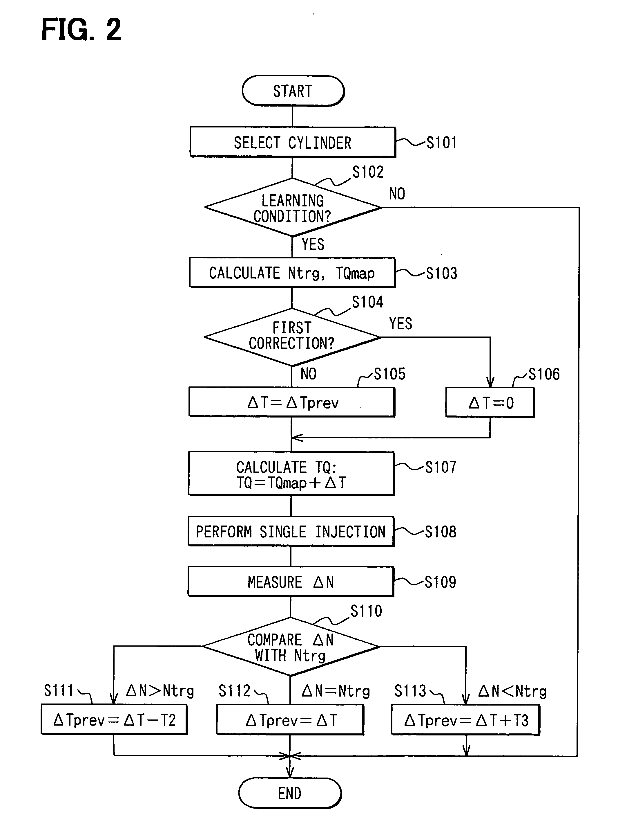
[0056]Next, an injection quantity learning operation performed by an ECU 6 according to a second embodiment of the present invention will be explained based on a flowchart shown in FIG. 5.

[0057]In the injection quantity learning operation according to the second embodiment, a modification speed of the injection period (a speed for modifying the injection period) is changed in accordance with a difference (an absolute value) between the engine state variation ΔN and the target value Ntrg.

[0058]The modification speed is associated with a learning data acquisition continuation number N. The learning data acquisition continuation number N is the number of times the ECU 6 continuously acquires the data based on a certain injection pulse width. As the ECU 6 acquires more data continuously based on the certain injection pulse width (or as the learning data acquisition continuation number N increases), time length of the injection quantity learning operation based on the certain injection p...


PUM


Abstract

An electronic control unit (ECU) of an engine calculates a first modification value for decreasing a correction value of an injection period when a state variation of the engine caused by a single injection is greater than a target value. The ECU calculates a second modification value for increasing the correction value when the state variation is less than the target value. The second modification value is greater than the first modification value. Thus, a period necessary to converge the correction value can be shortened when the correction value is increased. The first modification value is increased if a difference between the state variation and the target value exceeds a permissible value when the correction value is decreased. Thus, the injection quantity is decreased quickly to prevent excessive fuel injection.

Description

CROSS REFERENCE TO RELATED APPLICATION[0001]This application is based on and incorporates herein by reference Japanese Patent Application No. 2003-392114 filed on Nov. 21, 2003.BACKGROUND OF THE INVENTION[0002]1. Field of the Invention[0003]The present invention relates to an injection control system of an internal combustion engine for performing an injection quantity learning operation.[0004]2. Description of Related Art[0005]As a method of inhibiting generation of combustion noise and nitrogen oxides in a diesel engine, a method of performing a pilot injection for injecting a very small quantity of fuel before a main injection is known. Since a command value of the pilot injection quantity is small, improvement of accuracy of the small quantity injection is necessary to sufficiently exert the effects of the pilot injection of inhibiting the generation of the combustion noise and the nitrogen oxides. Therefore, an injection quantity learning operation for measuring a deviation bet...

Claims


Application Information

Patent Timeline
Patent Type & Authority Patents(United States)
IPC IPC(8): B60T7/12F02D45/00F02D41/12F02D41/14F02D41/24F02D41/34F02D41/38
CPCF02D41/1498F02D41/2467F02D41/2438F02D41/123F02D41/3845F02D41/2441
Inventor ASANO, MASAHIROTAKEMOTO, EIJIHARAGUCHI, HIROSHI
Owner DENSO CORP
Learn More