
Automatic power-driven toothbrushes

a power-driven toothbrush and automatic technology, applied in the field of dental hygiene devices, can solve the problems of difficulty in generating difficulty in providing a higher frequency of bristle movement of conventional power-driven toothbrushes, and many major limitations of conventional power-driven toothbrush manufacturers and designers, and achieve the effect of higher charging capacity

Inactive Publication Date: 2005-01-25
WONG MAN KWAN
View PDF4 Cites 89 Cited by
  • Summary
  • Abstract
  • Description
  • Claims
  • Application Information

AI Technical Summary

Benefits of technology

Specifically, it is an object of the present invention to provide an improved automatic power toothbrush driven by a direct coupling of the mechanical rotation to the electromagnetic force to generate vibrations of higher frequencies. More direct and efficient utilization of electric power is achieved with the DC motor rotation movement powered by the rechargeable batteries. Higher vibrating frequencies are also made available by employing this improved driving mechanism.
Another object of the present invention is to provide an improved automatic power toothbrush charged by a direct AC-to-AC current transformer charging circuit to provide higher charging capacity. The charging efficiency is further improved and optimized with a frequency converter to convert a regular AC current to a primary current of higher frequency to generate a secondary induced current applicable for efficiently charging the rechargeable batteries. Shorter charging period is achieved with higher charging capacity. The toothbrush can then be more economically employed by multiple users with multiple brush head when the charging period is shortened.

Problems solved by technology

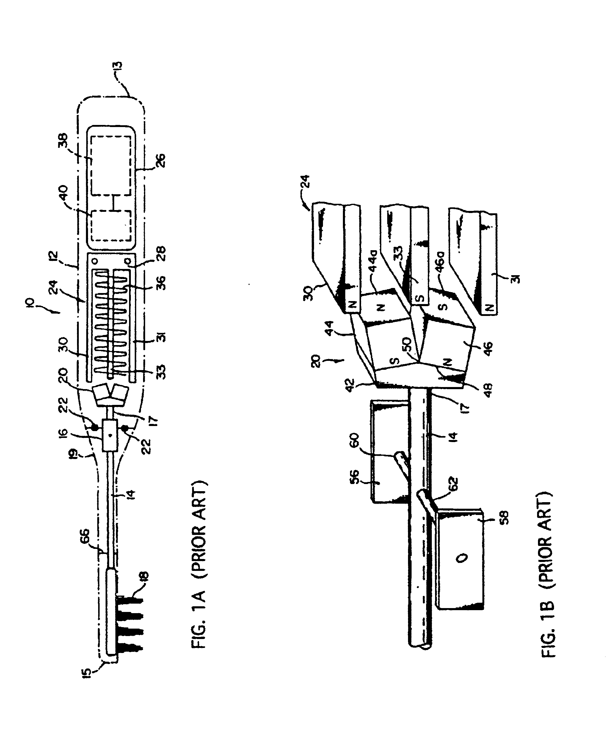
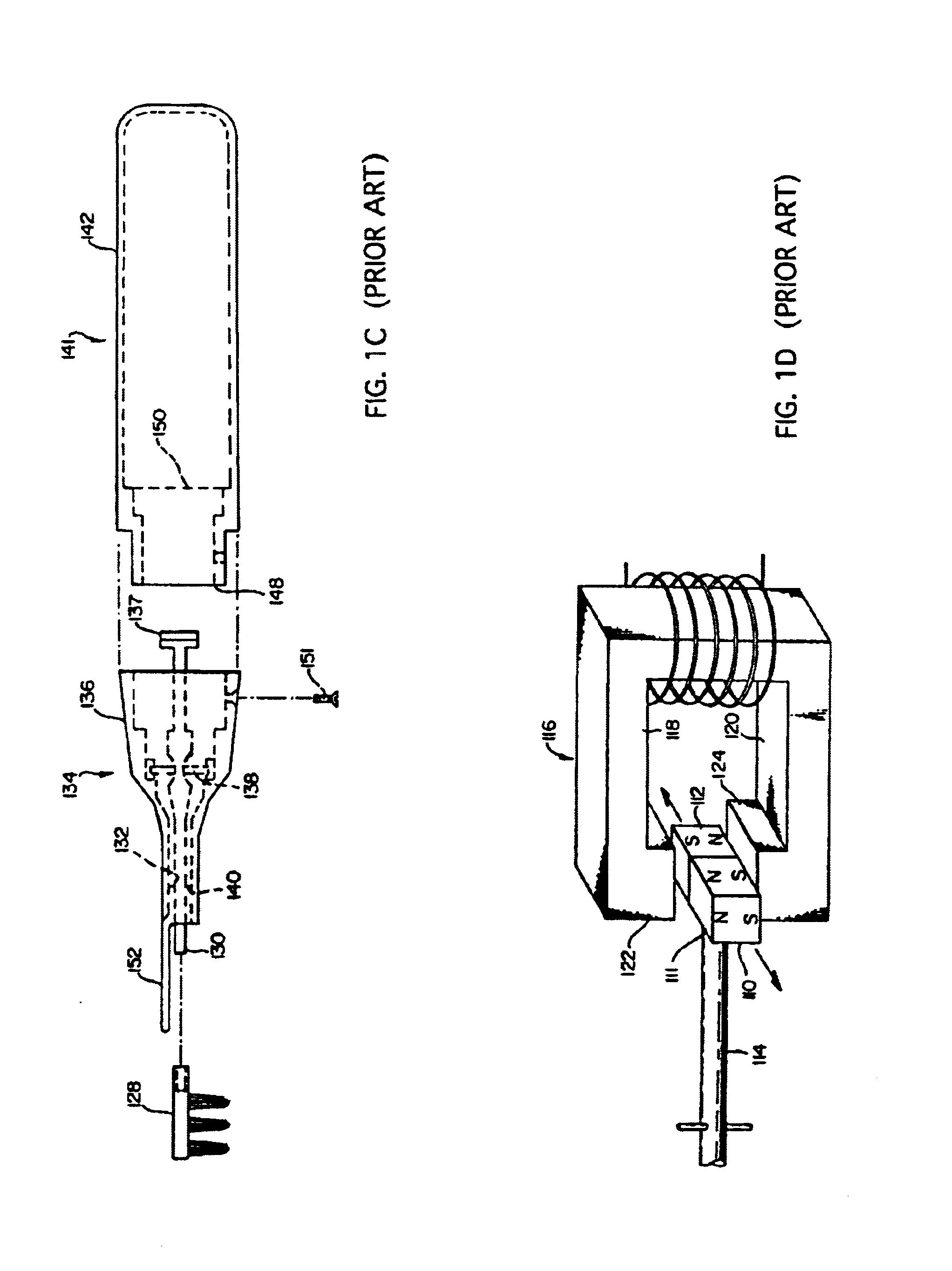
Several major limitations are faced by the manufacturers and designers of conventional vibrating or rotating toothbrushes driven by forces generated with input signals of continuously pulsed or alternating electromagnetic signals.
A first limitation is the difficulties in generating higher frequency of bristle movements to effectively remove dental plagues by brushing and acoustic cleaning.
Conventional power driven toothbrushes typically have difficulties in providing frequency of bristle movement higher than 10,000 cycles per minutes.
Technical limitations and cost considerations often prevent the frequency of a conventional automatic toothbrush to exceed a limit higher than 10,000 cycles per minute.
In addition to the limitations encountered for providing higher frequencies of movement, a feature of frequency control and adjustment when implemented in conventional toothbrushes would often require more complicate electromagnetic and mechanical designs and become quite costly.
Due to the cost consideration, generally, there is no user control or adjustment of brushing speed.
Furthermore, as rechargeable batteries are commonly used in the automatic power-driven toothbrushes, the application of the power-driven toothbrushes is often limited by requiring long period of recharging operation.
Such long hours of recharge requirement is caused by the low charging rates due to the ineffective battery charging methods commonly employed in conventional electric toothbrushes now available in the marketplace.
The driving forces generated by coupling the magnetic fields between the permanent magnets and the electromagnets are however inefficient utilization of the energy provided by the rechargeable battery.
The inefficiency of energy utilization is the results of energy losses in the air gap fluxes between the permanent magnets and the electromagnets.
Due to the constraints of the output voltage of the rechargeable battery, the maximum frequency of the oscillator is limited.
Thus a higher frequency of bristle movement is difficult to achieve because the limitation of the frequency of the oscillating circuit.

Method used


Image

  • Automatic power-driven toothbrushes
  • Automatic power-driven toothbrushes
  • Automatic power-driven toothbrushes

Examples


Embodiment Construction

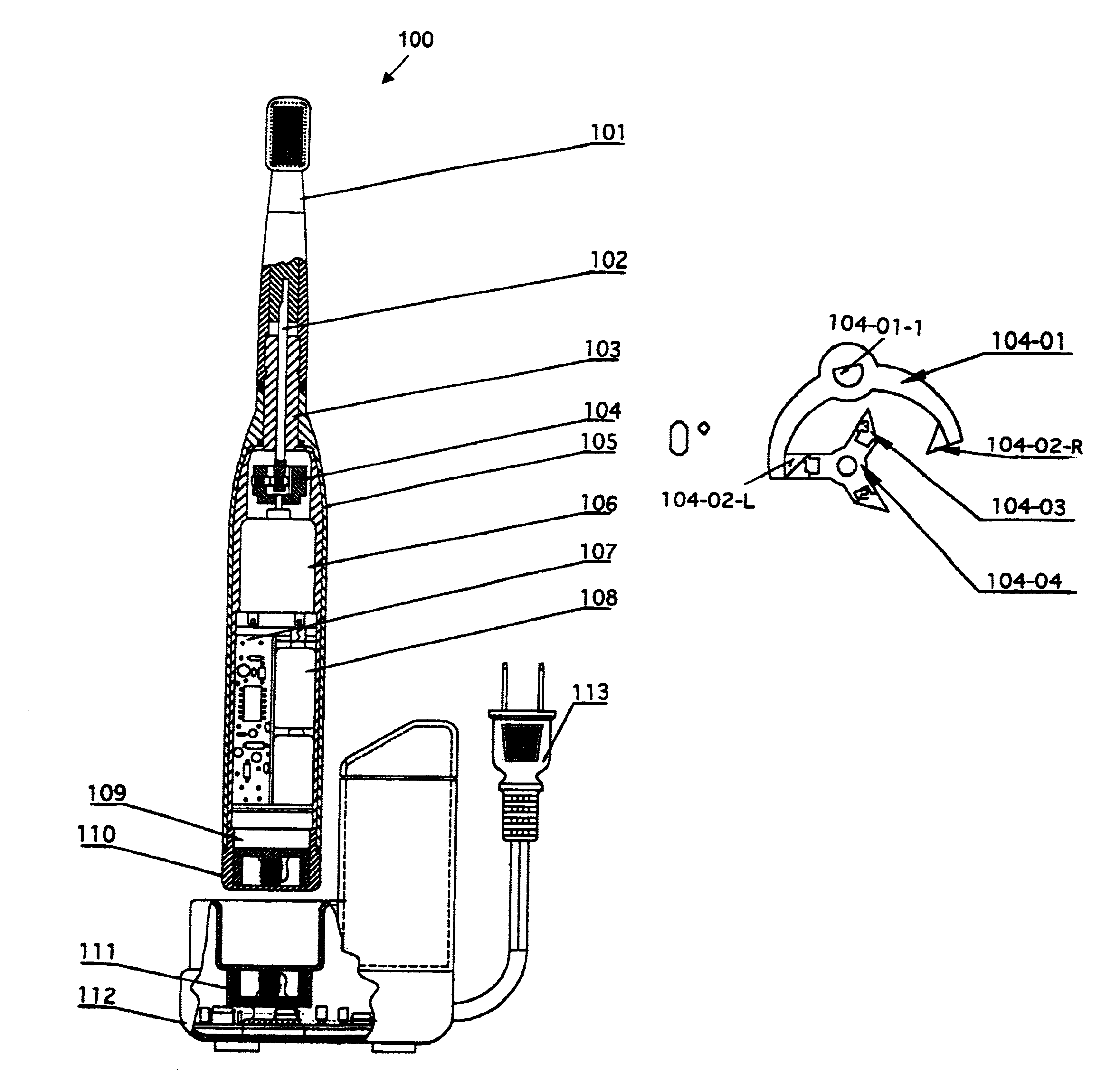
Referring to FIG. 2A for a cross sectional view of a vibrating toothbrush 100 of this invention. The toothbrush includes an elongated hollow case 105 for enclosing and protecting the electrical and mechanical components contained in the case and also functions as a handle that a user of the toothbrush can conveniently hold and control and move the toothbrush. The elongated hollow case 105 is generally circular in cross section and includes a lower body portion and upper neck portion. The lower body portion has a length of about ten to fifteen centimeters and a diameter ranging from 2 to 4 centimeters. The upper neck portion has a length of about three to five centimeters and a diameter of about 0.5 to 1.0 centimeter. A brush head 101 is then mounted onto the upper neck. The side view and front view of the brush head 101 is shown in FIGS. 2B and 2C respectively. The brush head 101 with the bristles is powered by the rechargeable batteries 108 to vibrate as that shown in FIGS. 2D and ...


PUM


Abstract

The present invention discloses the present invention discloses a power toothbrush that includes a body portion 105. An elongated level arm 102 extends from one end of the body portion to a toothbrush head 101 disposed at a distal end of the toothbrush. The toothbrush head includes a plurality of brush bristles. The elongated lever arm 102 is mounted on a vibrating pivot 104 driven by rotational DC motor engaging and pushing a set of permanent magnets attached to a two-arm fork rotating along the lever arm 102. In a preferred embodiment, the DC motor drives a three-leg permanent magnets each disposed at a 120-degree phase from each other for driving the two-arm fork for generating a vibration that three-times the frequency of the DC motor's rotational frequency.

Description

BACKGROUND OF THE INVENTION1. Field of the InventionThis invention relates generally to a dental hygiene device. More particularly, this invention relates to an electromagnetic power-driven toothbrush provided with improved electromagnetic-and-mechanical-coupled driving mechanisms and a novel and improved battery charging device with significantly higher charging efficiency.2. Description of the Prior ArtSeveral major limitations are faced by the manufacturers and designers of conventional vibrating or rotating toothbrushes driven by forces generated with input signals of continuously pulsed or alternating electromagnetic signals. A first limitation is the difficulties in generating higher frequency of bristle movements to effectively remove dental plagues by brushing and acoustic cleaning. Conventional power driven toothbrushes typically have difficulties in providing frequency of bristle movement higher than 10,000 cycles per minutes. Technical limitations and cost considerations ...

Claims


Application Information

Patent Timeline
IPC IPC(8): A61C17/22A61C17/34A61C17/16
CPCA61C17/22A61C17/3436A61C17/3418A61C17/224A61C2204/002
Inventor WONG, MAN-KWAN
Owner WONG MAN KWAN
Learn More