
Battery with resin integrated resin substrate

Inactive Publication Date: 2005-03-01
PANASONIC CORP
View PDF9 Cites 95 Cited by
  • Summary
  • Abstract
  • Description
  • Claims
  • Application Information

AI Technical Summary

Benefits of technology

The circuit substrate is integrated with the battery by the resin mold package, and the protection circuit element mounted on one side of the circuit substrate is covered by the resin mold package and insulated from the positive and negative terminals of the battery and leads connecting these terminals to the circuit substrate. In other words, the resin mold package has two functions: one is to connect and unite the battery and circuit substrate, and the other is to insulate and cover the protection circuit element. The external terminals are formed on the other side of the circuit substrate, and the substrate is integrated with the battery so that the external terminals face the outer side, where they serve as charge / discharge terminals of the battery. Batteries having such construction do not necessitate a retaining member for holding the circuit substrate when encased in an outer case of a battery pack, or a connection member for connecting the substrate with external terminals and the battery. This improves the freedom of design for the outer case, leading to a reduction in the period required for the development of new products, and allows for generalized use of outer cases. Further, since the structure of the battery pack is simplified, costs for the battery packs are accordingly reduced. Moreover, the resin mold package which provides insulation between thermal fuses or PTC elements mounted on plain batteries and circuit substrate, and between the leads connecting various constituents, enables high-density arrangement of battery elements, whereby volume efficiency of the battery is much improved.
Connecting the upper resin mold piece and the lower resin mold piece by forming a coupling resin mold piece will further improve the strength of the integral structure, as the separate resin mold pieces are coupled together. It will make the battery pack suitable for portable electronic devices which tend to be subjected to vibration and shocks.

Problems solved by technology

A temperature rise in the battery leads to rapidly built-up gas pressure resulting from chemical reactions between positive electrode active materials and electrolyte, or from evaporation or decomposition of electrolyte, which may cause fire or explosion of the battery.
Pack cases are usually manufactured by resin molding technology, and the fabrication cost of molding dies for the resin molding tends to be high, because of which pack cases generally cause high costs.
Moreover, the time required for designing the molding dies is relatively long, which makes difficult the application of battery packs to portable electronic devices such as mobile phones, which are re-modeled in short cycles.
Another problem is that battery packs allow themselves to be made smaller and thinner only to a limited extent because of the limitation on the thickness moldable in resin molding and because of the need to retain certain strength of the battery pack.
To mount electronic components such as the above-mentioned thermal fuse or PTC element on small batteries used as a power source for portable electronic devices, these need to be accommodated with the battery in a case in the form of a battery pack, which tends to cause high costs.
In order to provide such a temperature detection sensor, the rechargeable battery needs to be designed as a battery pack, which requires a larger number of steps in its manufacture process and tends to cause high costs because of the need to provide a structure to ensure precise detection of battery temperature.
Prismatic batteries have their positive and negative electrodes on the sealing end, but they are formed on different, stepped surfaces, causing the external connection structure to be complex.
When uniting a battery and a circuit substrate by resin molding, there was a problem that resin does not form good enough a form with the battery or substrate, and so it was necessary to encapsulate the battery and substrate by a resin mold package, resulting in a structure very similar to a battery pack in which a battery and a substrate are accommodated in a resin mold pack case.
This was contrary to the demand for smaller and thinner batteries.
Therefore, there is the risk that resin mold package may peel off from the battery if subjected to vibration or shocks.
If the dimensional precision is low, the contact resistance between the device-side connection terminals and external terminals will become high, leading to malfunctions such as contact failure and voltage drop.

Method used

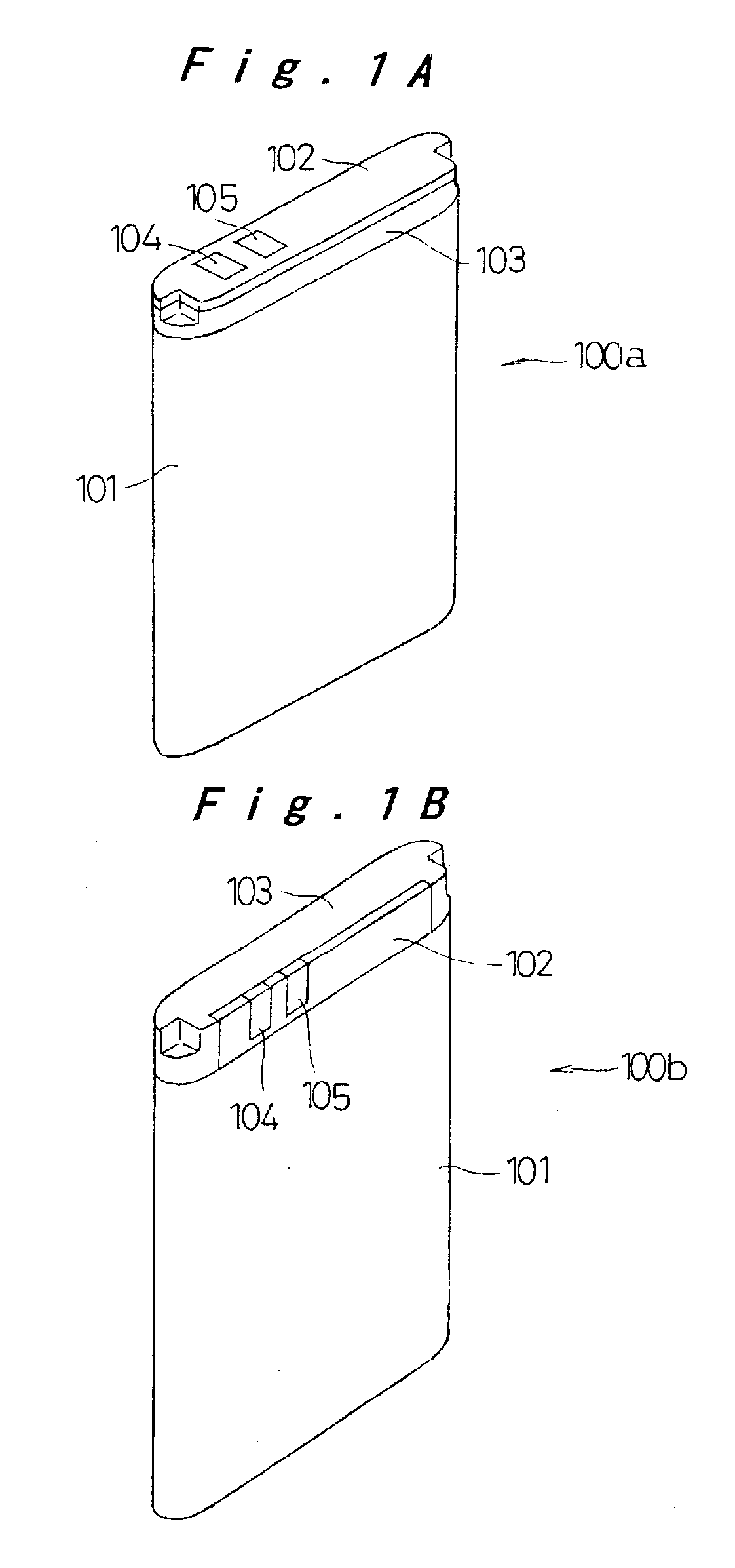
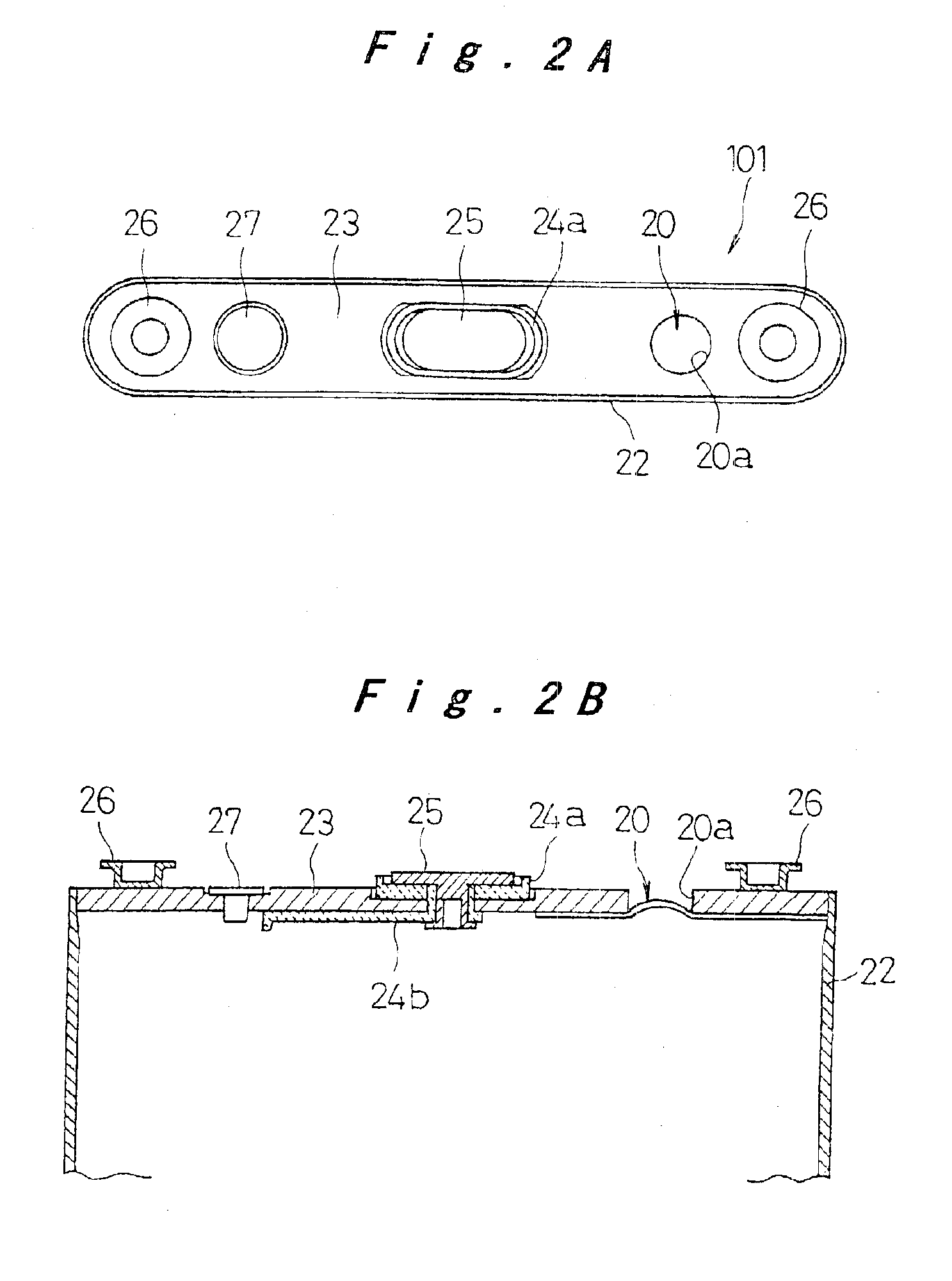
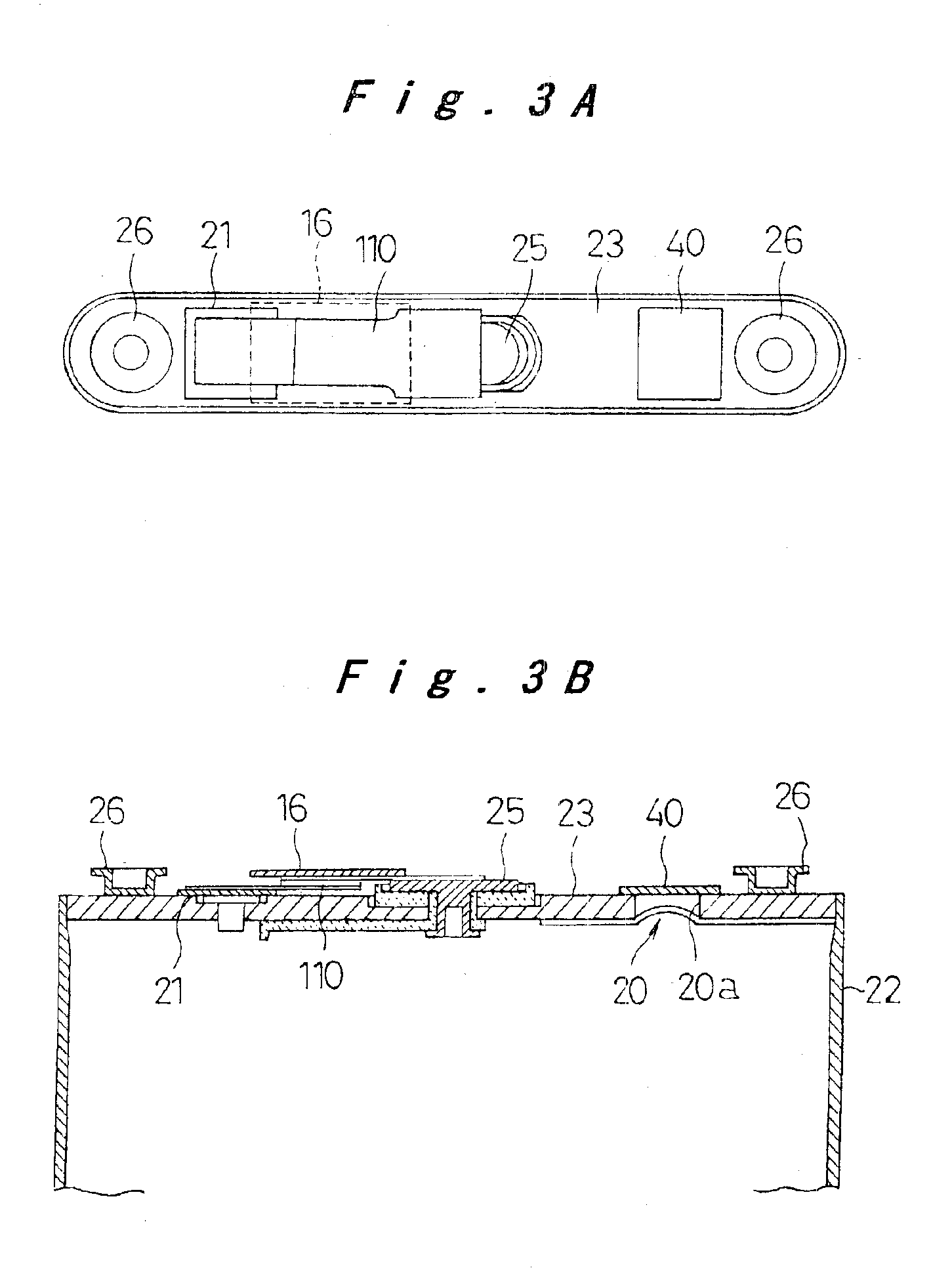

Image

  • Battery with resin integrated resin substrate
  • Battery with resin integrated resin substrate
  • Battery with resin integrated resin substrate

Examples


second embodiment

The following is a description of a battery pack according to the present invention. The battery pack of this embodiment is used for a mobile phone and constructed with a flat prismatic lithium ion rechargeable battery. Battery packs for mobile phones need to be small, light-weight, and thin, and in addition, they are desired to have a high energy density to exhibit a high functionality, a high mechanical strength to withstand impacts caused by a falling accident which is inevitable with a portable device, a structure which does not allow it to be easily disassembled, and safety features for protecting the rechargeable battery from short-circuiting, overcharge, and high temperature. The battery pack described below satisfies all these requirements.

FIG. 8 is an outer representation of a battery pack 1 according to this embodiment. On one end face of the flat battery pack are exposed external terminals 6 consisting of a positive terminal, a negative terminal, and a temperature detecti...

third embodiment

The following is a description of a battery pack according to the invention. The battery pack of this embodiment contains a plurality of rechargeable batteries.

FIG. 18 is an outer representation of the battery pack 200 according to the third embodiment. It contains two flat prismatic rechargeable batteries 2a, 2b connected in series to a circuit substrate 203 integrated therewith by a resin mold package 202 as shown in FIG. 19.

The rechargeable batteries 2a, 2b are constructed basically the same as the rechargeable battery 2 described above, except that additional engaging members 26, 26 are bonded to the bottom of the battery case 22 so as to ensure the bond between two rechargeable batteries 2a, 2b. The positive electrode connecting land on the circuit substrate 203 is electrically connected to the bottom of the battery case 22 of rechargeable battery 2b by a positive lead plate 204. The negative electrode connecting land on the circuit substrate 203 is electrically connected to th...


PUM


Abstract

A battery and a battery pack comprising a rechargeable battery (2) and a circuit substrate (3) integrated therein by a resin mold package (11) are provided. Resin is filled between the rechargeable battery (2) and the substrate (3) electrically connected thereto, so as to unite them as one battery or battery pack. The rechargeable battery (2) includes an engaging member (26) which functions as an anchor to the resin mold package (11) formed onto the battery, whereby the resin mold package (11) is firmly joined to the rechargeable battery (2). A thermo-sensitive element can be incorporated either on the circuit substrate (3) or within the space filled with resin.

Description

TECHNICAL FIELDThe present invention relates to a battery having an enhanced external connectivity and safety features, and to a small, thin battery pack with improved rigidity which is suitably used as a power source for portable electronic devices and the like.BACKGROUND ARTWith the remarkable development of small, thin, and high-functionality portable electronic devices, there is a growing demand for smaller, thinner, and high-capacity batteries and battery packs as the power source for these devices. Lithium batteries are known to be easily made small and to have high capacity. In particular, flat prismatic lithium ion rechargeable batteries that can be repeatedly used are suitable for the devices to be made thinner, and therefore they have been increasingly used as the rechargeable battery for portable electronic devices such as mobile phones.Since lithium batteries have high energy density and contain a flammable organic solvent as liquid electrolyte, it is essential to take a...

Claims


Application Information

Patent Timeline
IPC IPC(8): H01M2/10H01M6/00H01M6/50H01M10/48H01M50/209
CPCH01M2/1066H01M2200/10Y02E60/10H01M50/209H01M50/20H01M10/052
Inventor MASUMOTO, KENJINKOZU, KATSUMITSURUTA, KUNIO
Owner PANASONIC CORP
Learn More