
Combination filter for filtering fluids

a technology of filter fluid and filter system, which is applied in gravity filters, filtration separation, separation processes, etc., can solve the problems of undesirable high pressure drop and high pressure drop of vehicle cabin filter systems, and achieves flat increase in pressure drop, long life, and low pressure drop

Inactive Publication Date: 2006-01-17
3M INNOVATIVE PROPERTIES CO
View PDF49 Cites 66 Cited by
  • Summary
  • Abstract
  • Description
  • Claims
  • Application Information

AI Technical Summary

Benefits of technology

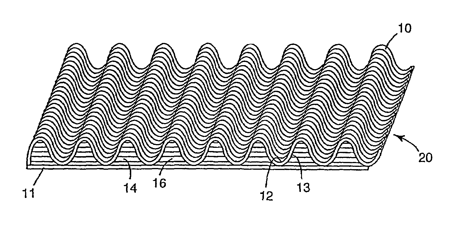
[0015]The combination filters according to the invention exhibit an advantageously low pressure drop over its lifetime. In other words the combination filters according to the invention show a relatively flat increase in pressure drop with loading over the lifetime of the filter, and hence, a corresponding long lifetime and high capacity.

Problems solved by technology

Although the active carbon particle pad exhibits good gas efficiency and / or gas capacity depending on the thickness and carbon content of the pad, the application of such an active carbon particle pad causes a high pressure drop.
A high pressure drop is undesirable for vehicle cabin filter systems.
Although such a combination filter has an acceptable pressure drop, the lifetime thereof is limited, i.e. the filter needs to be replaced frequently.

Method used


Image

  • Combination filter for filtering fluids
  • Combination filter for filtering fluids
  • Combination filter for filtering fluids

Examples


example 1

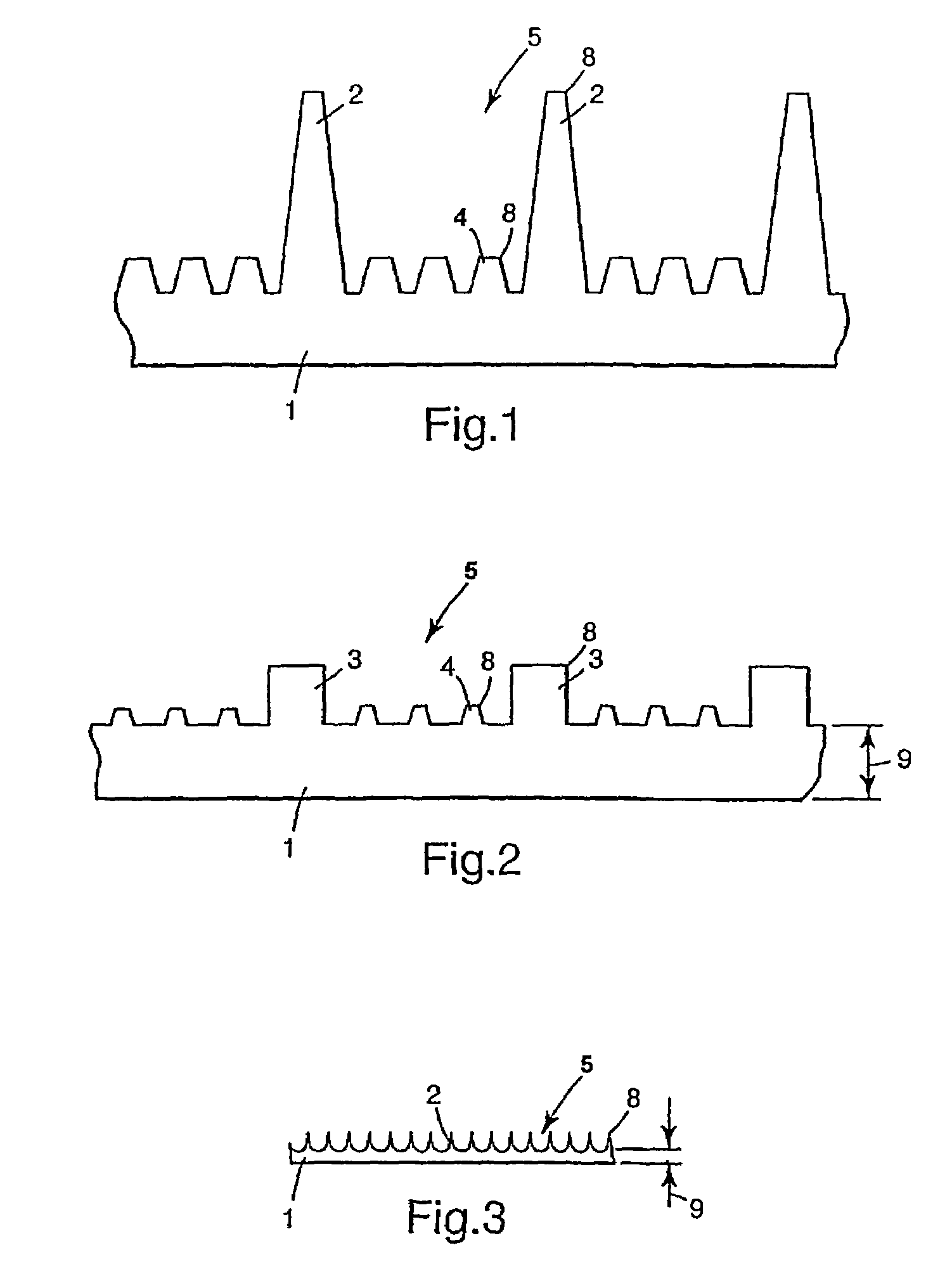
[0069]The flow channel particulate filtration media of a combination filter was produced using the following method: Polypropylene resin was formed into a structured film using standard extrusion techniques by extruding the resin onto a casting roll with a micro-grooved surface. The resulting cast film had a first smooth major surface and a second structured major surface with longitudinally arranged continuous features from the casting roll. The features-on the film consisted of evenly spaced first primary structures and interlaced secondary structures. The primary structures were spaced 150 microns apart and had a substantially rectangular cross-section that was about 75 microns tall and about 80 microns wide (a height / width ratio of about 1) at the base with a side wall draft of about 5°. Three secondary structures having substantially rectangular cross-sections that were 25 microns tall and 26 microns wide at the base (height / width ratio of about 1) were evenly spaced between th...

example 2

[0076]For this combination filter the same flow channel particulate filtration media was used as in Example 1 and specified above.

[0077]For the gas adsorbing filtration media agglomerates were prepared, 110 grams of treated activated carbon granules, 12×20 mesh (coconut derived activated GG carbon available from Kuraray in Okayama, Japan) were heated at 165° C. for 45 minutes. The granules were treated with an aqueous solution of K2CO3 to improve the absorption of acid gas. These heated granules were then dry-mixed with 20 grams of polyurethane of a particle size in the range of 50–225 microns (Morton PS 455-100, MORTON-THIOKOL, Seabrooke, N.H.) for 24 seconds in a mechanical mixer. The resultant carbon granule agglomerates adhered with binder particles were sieved through a series of sieves with mesh sizes between 7–12. The sieved agglomerates were then layered loosely in a mold with the dimensions 255×190 mm and heated at 165° C. for 40 minutes without compression. This results in...

example 3

[0078]For this combination filter the same flow channel particulate filtration media and gas adsorbing filtration media of Example 2 were used except for the porous layer of agglomerated carbon particles was provided with channels extending in the flow direction. 400 of channels having a diameter of 1 mm were homogeneously distributed across the width and length dimensions of the layer.


PUM

PropertyMeasurementUnit
Thicknessaaaaaaaaaa
Thicknessaaaaaaaaaa
Diameteraaaaaaaaaa

Abstract

The present invention provides a combination filter for filtering fluids comprising a flow channel particulate filtration media having a first face and a second face and a gas adsorbing filtration media. The flow channel particulate filtration media comprises a plurality of flow channels directed in flow direction and defined by inner surfaces. The flow channels having inlet openings through the first face and outlet openings through the second face of the flow channel particulate filtration media. The inner surfaces of said flow channels at least in part are provided with structures protruding therefrom and forming or extending into the flow channels or an electrical charge or a combination of both. The said gas adsorbing filtration media comprises a pad having a first face and a second face and width and length dimensions orthogonal with respect to each other and each individually to the flow direction and having a thickness dimension in flow direction. The pad comprising a layer extending substantially perpendicular to the flow direction across the width and length dimensions of the pad.

Description

TECHNICAL FIELD[0001]The present invention relates to a combination filter system for filtering fluids, particularly gases, particularly for filtering air streaming into the passenger cabin of a vehicle.BACKGROUND OF THE INVENTION[0002]Combination filter systems for filtering air streaming into the passenger cabin of a vehicle are known. Such filter systems typically comprise a particulate filter media with a sorbent filter media.[0003]For example, WO-A-95 / 26802 discloses a combination filter system which comprises a pleated electret charged fiber / nonwoven filter media and an active carbon particle pad. Although the active carbon particle pad exhibits good gas efficiency and / or gas capacity depending on the thickness and carbon content of the pad, the application of such an active carbon particle pad causes a high pressure drop. A high pressure drop is undesirable for vehicle cabin filter systems.[0004]EP-A-383236 discloses an adsorber particle layer that is co-pleated with an elect...

Claims


Application Information

Patent Timeline
IPC IPC(8): B01D29/07B01D46/12B01D53/04B01D53/02B01D46/00B01D46/10B01D46/24B01D46/52
CPCB01D46/0036B01D46/10B01D46/2411B01D46/521B01D53/0446B01D53/02B01D2275/10B01D2253/102B01D2253/342B01D46/52
Inventor DOMINIAK, KLAUSKOEHLER, FRANKBOCHYNEK, NICOLAILOTGERINK-BRUINENBERG, MARCUS
Owner 3M INNOVATIVE PROPERTIES CO
Learn More