Part transfer apparatus, control method for part transfer apparatus, IC test method, IC handler, and IC test apparatus

a control method and part transfer technology, applied in the direction of semiconductor/solid-state device testing/measurement, instruments, furnaces, etc., can solve the problems of inability to independently correct positions, extreme difficulty in simultaneously correcting the position of both pick-up heads, and changing the length of mechanical parts of the internal mechanism, so as to reduce the effect of vibration and stably perform the process

Inactive Publication Date: 2006-01-10
SEIKO EPSON CORP
View PDF9 Cites 4 Cited by
  • Summary
  • Abstract
  • Description
  • Claims
  • Application Information

AI Technical Summary

Benefits of technology

[0014]Because each of the holding and transfer mechanisms operates independently with (1) and (2) above, an operation is possible whereby when transferring parts held in the holding device to a specific position, the other holding and transfer mechanism can be made to wait with a part held in each holding device while the one holding and transfer mechanism is transferring, and index time can be shortened. Furthermore, because each shaft is rotationally driven by respective independent drive systems, the effects of vibration on each other can be prevented.
[0052]With (27) condensation on the tested ICs can be prevented when the electrical characteristics tests are performed at a low temperature.

Problems solved by technology

A problem with the transfer apparatus described above is that because pick-up heads 107 and 108 are connected to the same drive shaft 102, positioning pick-up head 107 on the test unit side and positioning pick-up head 108 on the supply / eject side must be accomplished simultaneously, and the positions cannot be independently corrected.
This set temperature can be appropriately changed and the above-noted mechanism operates under each set temperature, but when the temperature difference between the previous temperature setting and the current temperature setting is great, the length of mechanical parts of the internal mechanism changes due to thermal expansion or contraction, and there is the problem that the pick-up head position changes from the last adjusted position.
It is therefore necessary to correct this shift, but it is extremely difficult to correct the position of both pick-up heads simultaneously.
There is the further problem that a stable measurement environment free of vibrations, for example, is desirable for electrical measurements of electronic parts in the test unit, but while one pick-up head is operating at the test unit the other pick-up head is operating to eject a tested electronic part and supply the next part, and because high speed is required in the ejection and supply operation accompanying vibrations from the supply unit and ejection unit can be transferred to the pick-up head on the test unit side, and could possibly have some adverse effect on electronic part measurements, for example.

Method used


Image

  • Part transfer apparatus, control method for part transfer apparatus, IC test method, IC handler, and IC test apparatus
  • Part transfer apparatus, control method for part transfer apparatus, IC test method, IC handler, and IC test apparatus
  • Part transfer apparatus, control method for part transfer apparatus, IC test method, IC handler, and IC test apparatus

Examples


Embodiment Construction

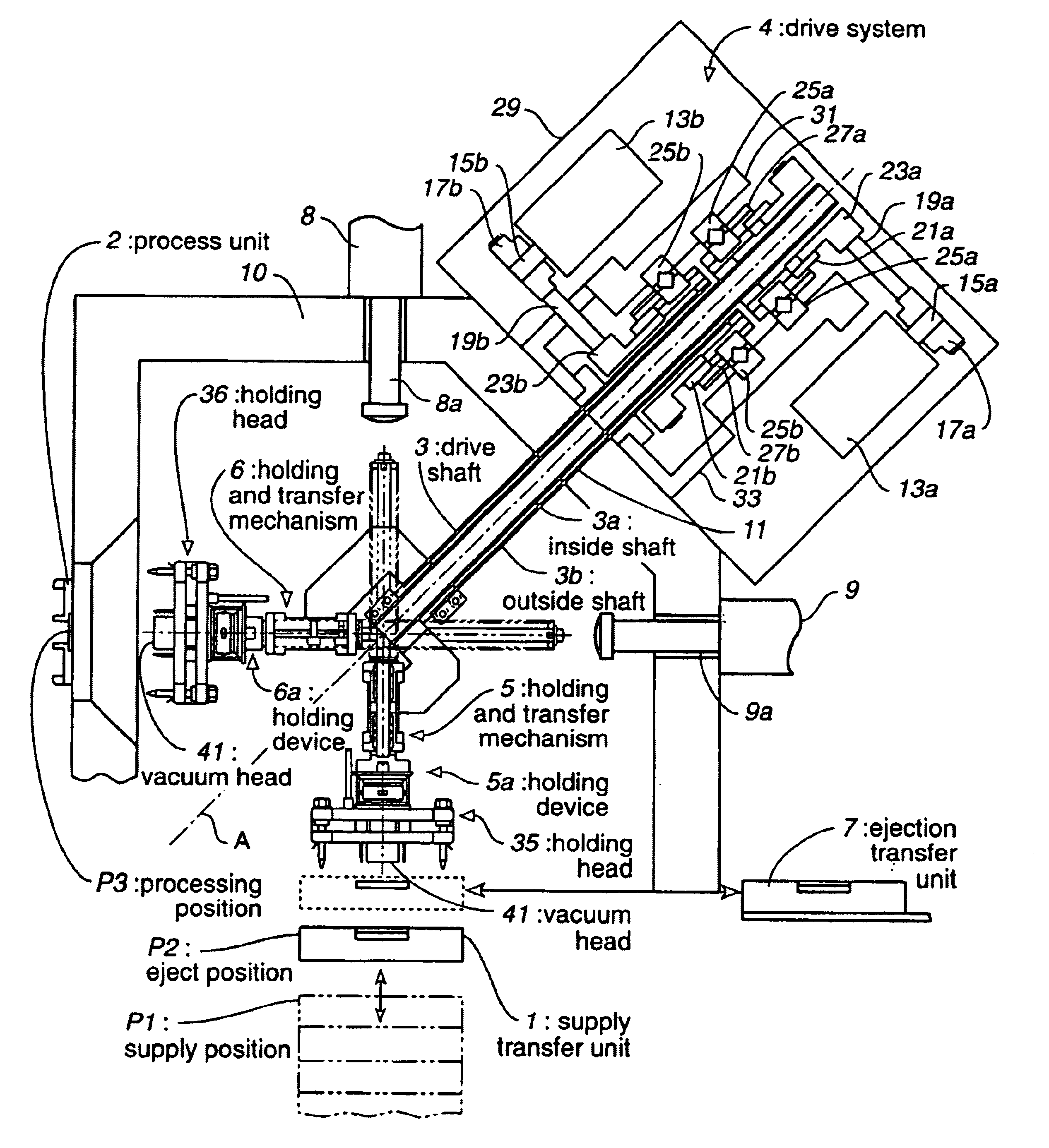
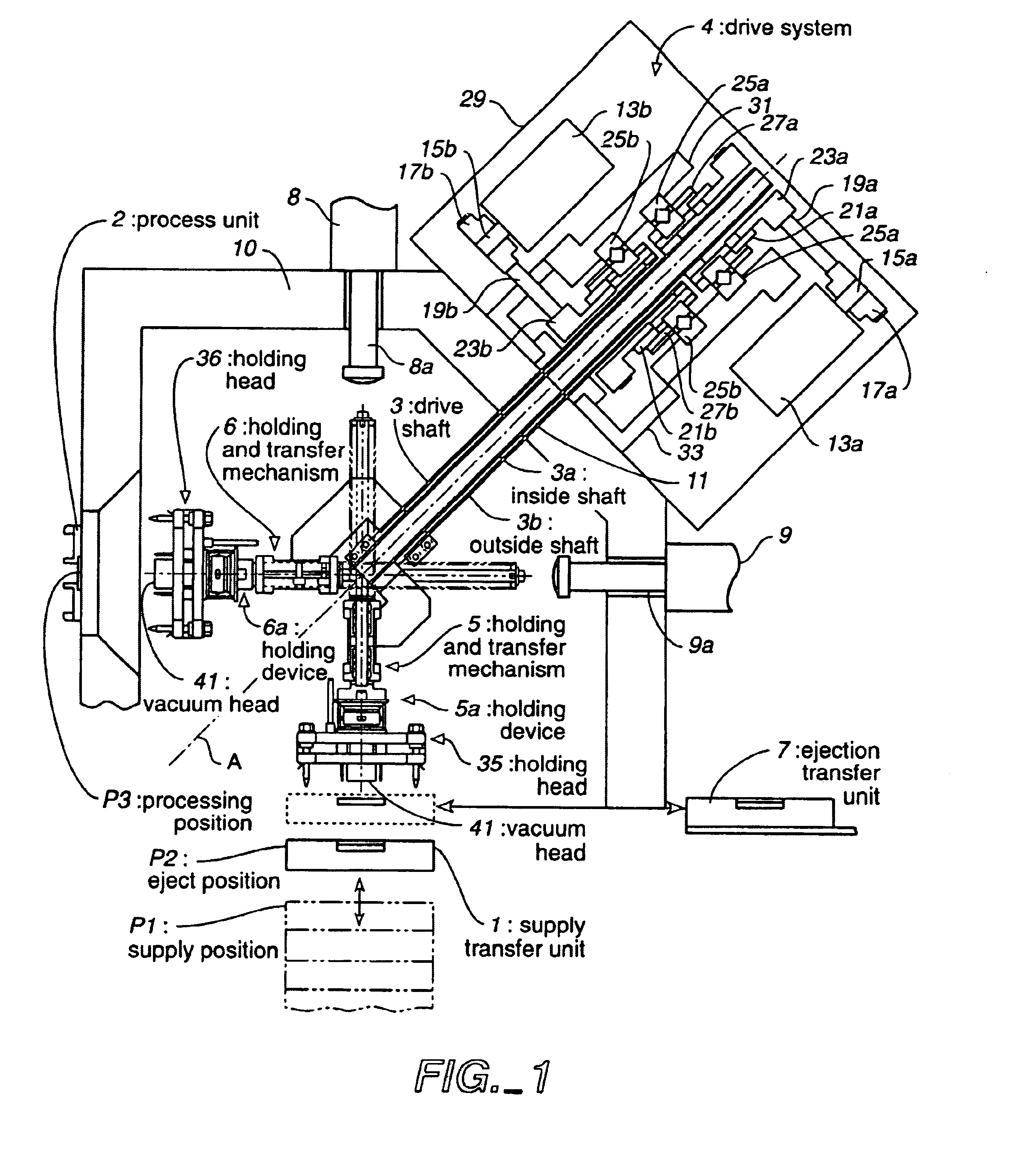
[0075]FIG. 1 is a front section view of a part transfer apparatus according to a preferred embodiment of the present invention, FIG. 2 is a front section view of the holding and transfer mechanism shown in FIG. 1, FIG. 3 is a side view of FIG. 2, FIG. 4 is an oblique schematic view of the holding and transfer mechanism shown in FIG. 1, and FIG. 5 is a block diagram of the configuration shown in FIG. 1. This embodiment is described using as an example of a part transfer apparatus an IC handler for transferring an IC device as a part from a supply transfer unit to a process unit performing an electrical characteristics test as a specific process. Inside the chamber insulation wall is temperature controlled to a set embodiment so that the electrical characteristics tests are performed at a high temperature or low temperature with this IC handler.

[0076]As shown in FIG. 1 this IC handler has a supply transfer unit 1 for supplying untested ICs, a process unit 2 for testing the electrical ...


PUM

PropertyMeasurementUnit
angleaaaaaaaaaa
angleaaaaaaaaaa
angleaaaaaaaaaa

Abstract

A configuration having two drive shafts, a drive system 4 connected to one end of each drive shaft for rotationally driving the respective drive shaft, and a holding and transfer mechanism 5, 6 connected to the other end and having a holding device 5a, 6a for holding an IC, each holding and transfer mechanism 5, 6 being able to operate independently.

Description

TECHNICAL FIELD[0001]The present invention relates to a part transfer apparatus, to a control method for a part transfer apparatus, to an IC handler, and to an IC test method, and relates particularly to a part handling apparatus for supplying and removing electronic parts to an electrical test step or other such process, to a control method for a part handling apparatus, to an IC test method, to an IC handler, and to an IC test apparatus.RELATED ART[0002]IC handlers have conventionally been used to sequentially position and test a large number of IC devices in a test position in processes for inspecting integrated circuit (IC) characteristics. The IC handler has a holding device for vacuum chucking the IC devices. This holding device repeats an operation whereby the IC is held in the supply transfer unit, the held IC device is supplied to an inspection socket disposed to the inspection position, and when testing the electrical characteristics of the IC device is completed, the IC d...

Claims


Application Information

Patent Timeline
Patent Type & Authority Patents(United States)
IPC IPC(8): G01R31/26B23Q7/04B23Q7/14G01R31/28H01L21/66
CPCG01R31/2887Y10T29/49004G01R31/26H01L22/00
Inventor FUJIMORI, HIROAKIMAEDA, MASAMI
Owner SEIKO EPSON CORP
Why Eureka
Try Eureka