
Stalk strength tester

Inactive Publication Date: 2006-01-10
MUCKLER GREGORY A
View PDF13 Cites 24 Cited by
  • Summary
  • Abstract
  • Description
  • Claims
  • Application Information

AI Technical Summary

Benefits of technology

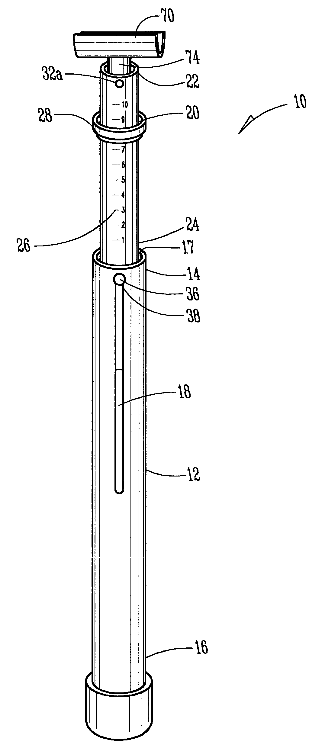
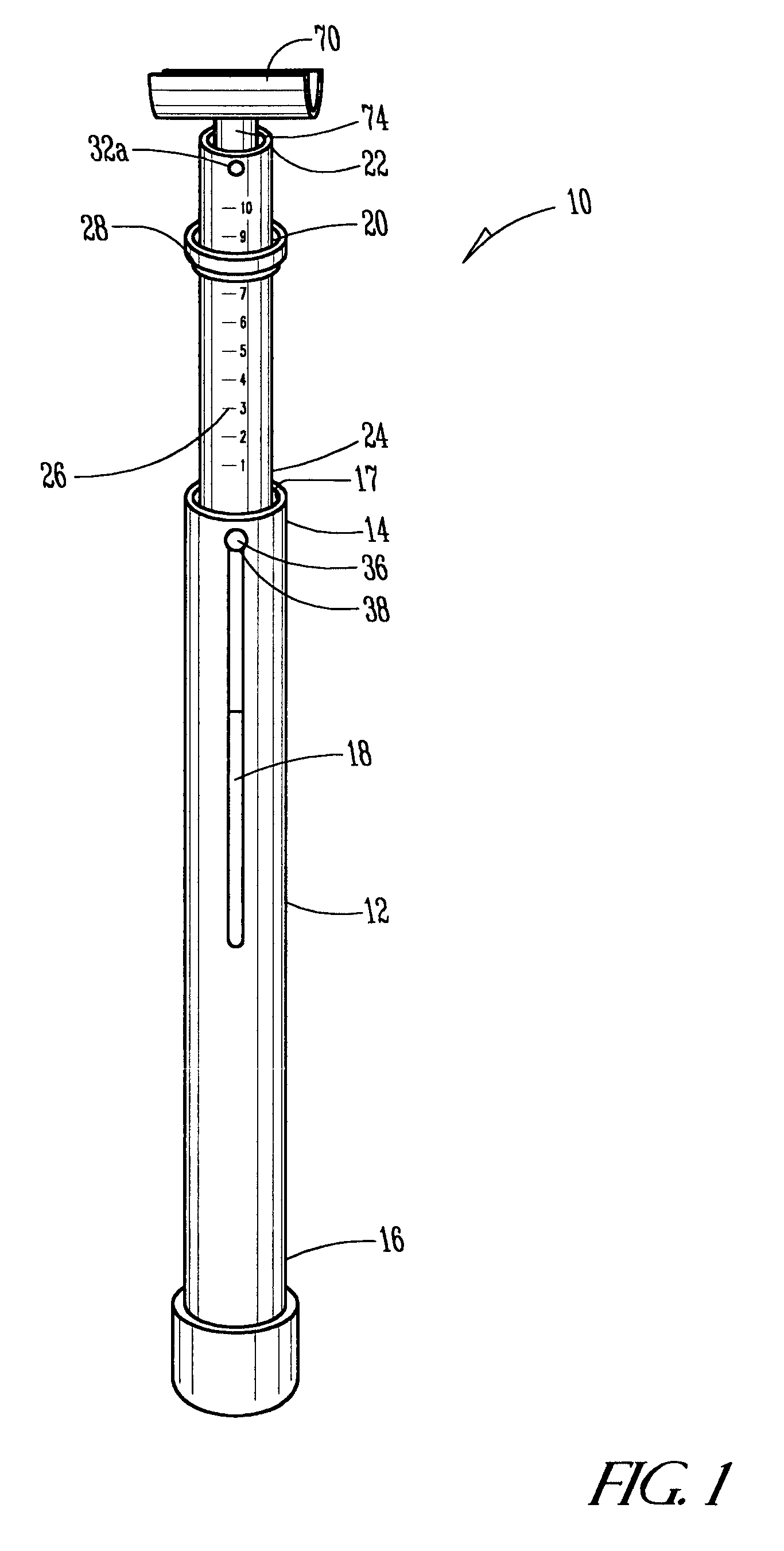
[0011]The present invention provides a stalk strength tester which is hand-held, can be calibrated, and minimizes the breakage of stalks being tested. The tester is constructed using an internal shaft and an external shaft in telescopic relationship with one another. Associated with the internal shaft is a tension element which can be calibrated such that a plurality of testers can be depended upon to provide consistent measurements. The telescopic relationship of the internal and external shaft is maintained by inserting a securing element through a slot in the external shaft and affixing it to the internal shaft while allowing the shafts to be remain slidable relative to one another.
[0012]Near an upper end of the internal shaft and above said external shaft when in resting position is a set of measurement markings and a frictionally engaged slidable marker. Pivotally attached to the upper end of the internal shaft is a trough-like cradle. The cradle's trough-like shape is used to provide alignment of the generally vertically growing stalk the strength of which is to be measured and the pivotal nature of the cradle allows the stalk to bend and slide out of the cradle just prior to its breaking point.

Problems solved by technology

This conductivity provides a measure of the moisture in the kernels but does not allow testing of moisture or strength of stalks.
If it is not strong enough, the stalk will break.
Although other devices have been disclosed for measuring tension in general, such as weighing scales, the disclosures of these devices do not contemplate their use for measuring tension in plant stalks nor would these devices be aperable for that purpose.
However, this device would not work for stalk strength measurements because it is not designed to be hand-held, or used horizontally or to press, but not break, stalks of a given strength.
None of the above-mentioned devices provide a device which allows measurement of the strength of plant stalks.

Method used


Image

  • Stalk strength tester
  • Stalk strength tester
  • Stalk strength tester

Examples


Embodiment Construction

)

[0024]Referring to FIG. 1, a first embodiment of the Stalk Strength Tester of the present invention is shown generally at 10. The tester 10 comprises an external shaft 12 with a first end 14, a second end 16, an interior 17, and a lengthwise slot 18, an internal shaft 20 including an upper end 22, a lower end 24, a set of measurement markings 26, and a slidable marker 28. In the preferred embodiment, the internal shaft 20 includes a set of opposing apertures 30a and 30b and a set of aligned apertures 32a and 32b.

[0025]The internal shaft 20 and the external shaft 12 are in telescopic relationship with one another. Means 34 for slidably maintaining the telescopic relationship of the internal shaft 20 and external shaft 12 is provided. In the first embodiment of the present invention, the means 34 comprises a first pin 36 affixed to the internal shaft 20 and protruding through the lengthwise slot 18 in the external shaft 12 and slidably secured by a head 38. In a second embodiment of...


PUM


Abstract

The stalk strength tester of the present invention includes an internal shaft and an external shaft in telescopic relationship. Pivotally associated with the upper end of the internal shaft is a trough-like stalk cradle. A set of measurement markers are on the upper end of the internal shaft and a rubber ring is around the internal shaft and abuts the external shaft. Associated with the other end of the internal shaft is a tension member. A tension adjustment structure is provided for adjusting the tension in the tension member. In operation, a stalk is positioned into the cradle and the tester is pushed against it. The internal shaft telescopically slides against the tension member and into the external shaft until the cradle pivots at which time the rubber ring remains in a position relative to one of the markers as an indicator of the tension measured.

Description

BACKGROUND OF THE INVENTION[0001]1. Field of the Invention[0002]The present invention relates in general to a device for determining stalk strength of crop plants and, more specifically, to a stalk tension measuring device which is calibrated, preferably spring loaded, and equipped to measure tension without breaking the stalks tested.[0003]2. Description of the Prior Art[0004]It is known in the art to use devices to assist in determining stalk strength and moisture levels in plants. Such information can be used to help determine readiness of the plants for harvest or to simply examine and compare the stalk strength of plants.[0005]U.S. Pat. No. 4,954,783 discloses a corn moisture tester, which operates by enclosing an ear of corn in a close-able sleeve. Upon closure of said sleeve around the ear of corn, conductor blades or electrodes pierce the kernels and the electrical conductivity is measured. This conductivity provides a measure of the moisture in the kernels but does not allo...

Claims


Application Information

Patent Timeline
IPC IPC(8): A01D75/18
CPCA01D75/00G01N3/00G01N33/0098G01N19/10G01N2203/0089
Inventor MUCKLER, GREGORY A.
Owner MUCKLER GREGORY A
Learn More