
Air heated, flexible door panel

a door panel and flexible technology, applied in the field of top supported doors, can solve the problems of door system drive mechanism or seal damage, door system failure to open altogether, economic inefficiencies, etc., and achieve the effect of reducing the manufacturing steps, facilitating flexing, and reducing the cost of each door panel

Inactive Publication Date: 2006-01-10
JAMISON DOOR
View PDF42 Cites 14 Cited by
  • Summary
  • Abstract
  • Description
  • Claims
  • Application Information

AI Technical Summary

Benefits of technology

[0008]In one particular aspect of the invention, a resilient door panel is used in a closure system. A seal formed between a doorframe and the door panel is effectively achieved by attracting the door panel to the doorframe either pneumatically or magnetically. Eliminating the need for rigid components in the door panel enables the use of numerous manufacturing approaches, such as bagged foam sheets, bagged poured foam door panels, and even unbagged foam doors that self-skin. Thereby, the manufacturing steps are greatly reduced and thus the cost of each door panel.
[0009]In another aspect of the invention, an approach to keeping the door seals free of ice is provided that is particularly suitable to resilient door panels. In particular, since the resilient door panel readily flexes, it is desirable to eliminate electrical wiring in the door panel that may be damaged during impact. Thus, heating of a door panel periphery by electrical resistive heating is eliminated;
[0011]In yet a further aspect of the invention, an automated door system includes a door position sensor that senses the door panel being in a closed position with a periphery of a door panel registered to a doorframe. A door positioning system responds to the door position sensor indicating that the door has been impacted by resetting the door panel to an open position, thereby mitigating possible damage to the door system.

Problems solved by technology

Otherwise, the door system drive mechanism or the seal may be damaged in attempting to overcome a frozen seal.
The door system may fail to open altogether if sufficiently stuck to stall the drive mechanism.
Other problems associated with frost accumulation include achieving a poor seal with the resulting economic inefficiencies and safety and appearance issues related to accumulating ice and moisture.

Method used


Image

  • Air heated, flexible door panel
  • Air heated, flexible door panel
  • Air heated, flexible door panel

Examples


Embodiment Construction

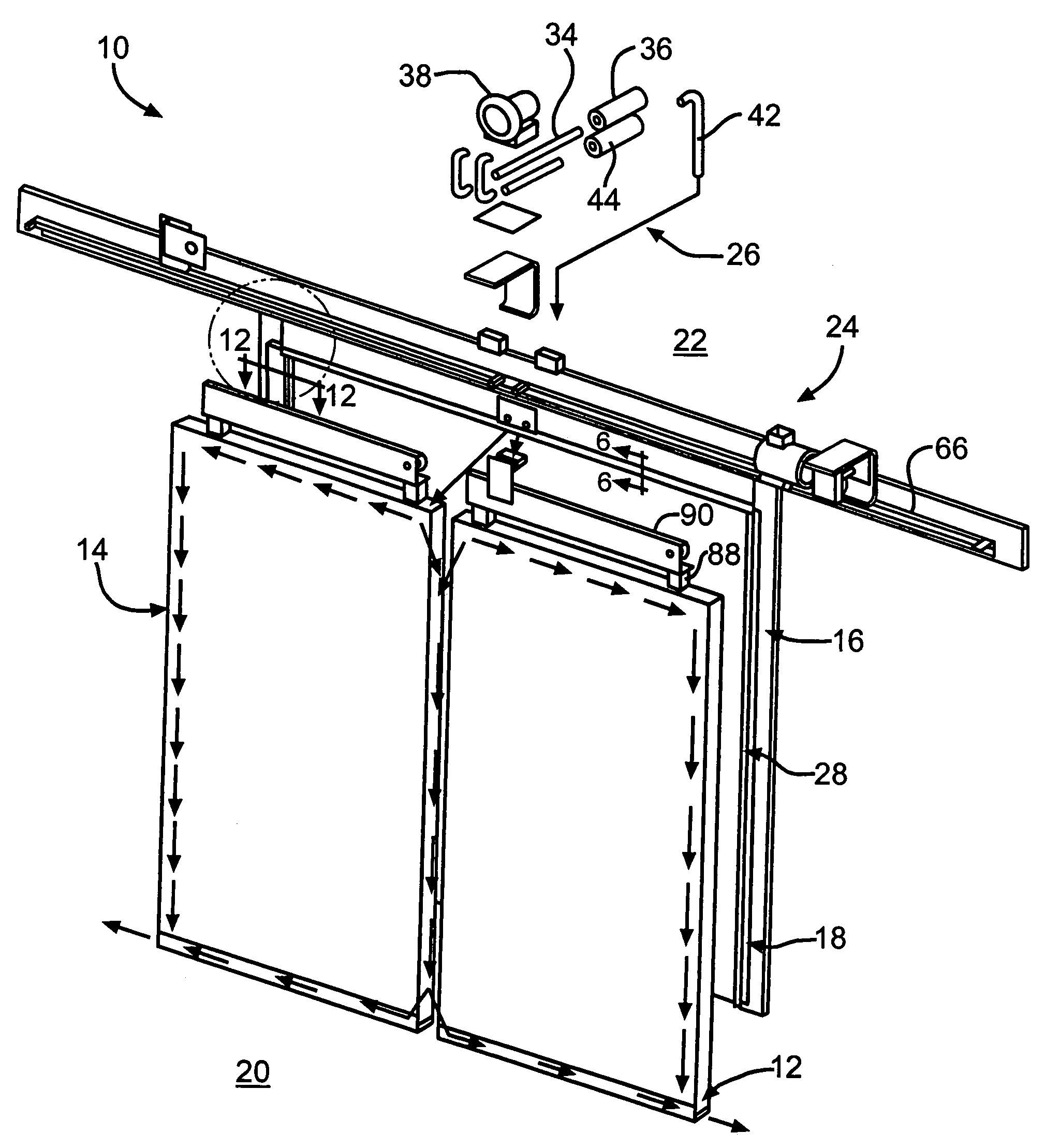
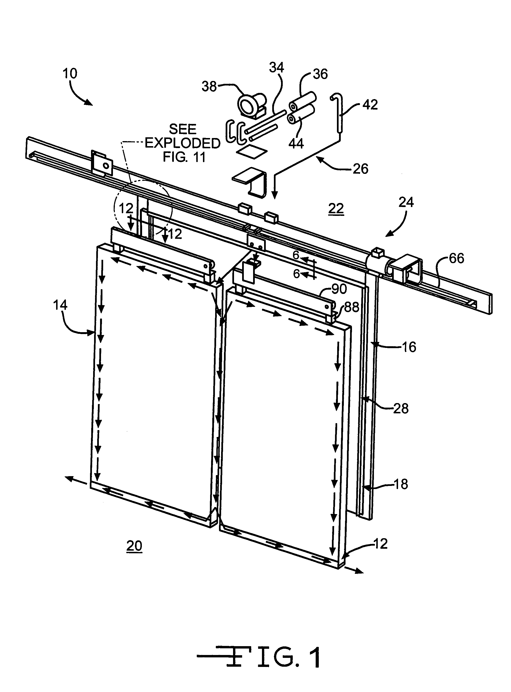
[0040]Turning to the Drawings wherein like numbers denote like components throughout the several views, in FIGS. 1–3, a closure system, depicted as a bi-parting horizontal sliding door system 10, advantageously includes fully resilient door panels 12, 14 for damage resistance that are affirmatively sealed to a doorframe 16 by an attraction sealing system, depicted as a magnetic sealing system 18, to effectively separate a warm space 20 from a cold space 22 (e.g., a cold storage locker). As shown particularly in FIG. 1, the door panels 12, 14 are supported by and power actuated by an overhead carriage 24, as is generally understood by those skilled in the art.

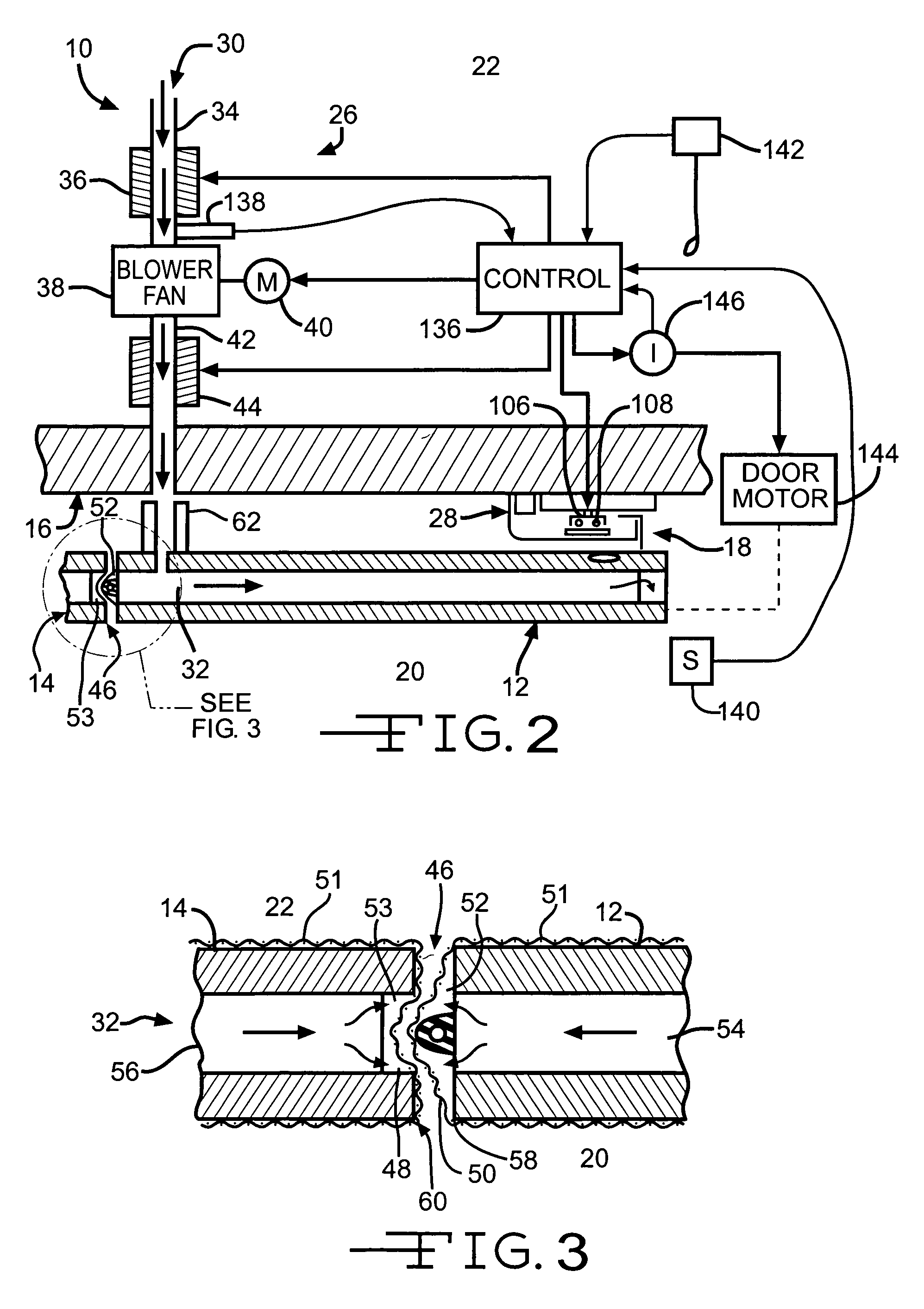
[0041]With particular reference to FIG. 2, the sliding door system 10 advantageously includes a frost control system 26 for preventing accumulation of ice on a sealing gasket 28 on the doorframe 16. Cold air from the cold space 22 passes through and is warmed by an air passage 30 that includes an air channel 32 in a periphery of...


PUM


Abstract

A door system for a cold storage locker has increased resistance to damage by including resilient door panels that flex when hit by a forklift. A high degree of insulation is achieved by the choice and thickness of the resilient foams therein. Also, the resilient door panels are magnetically attracted to a gasket seal on a doorframe to provide an affirmative seal. Active magnetic control may enhance the attraction or repulsion of the door panel. Frost control is realized by warming air from the cold storage locker and passing it through air channels in the door panel proximate to the gasket seal and down an astragal interface between door panels.

Description

FIELD OF THE INVENTION[0001]The present invention relates, in general, to top-supported doors, and more particularly to resilient doors suitable for cold storage rooms.BACKGROUND OF THE INVENTION[0002]So-called horizontal sliding doors include at least one door panel that is suspended by a carriage that travels along an overhead track. The door panel may be manually or automatically moved from a blocking position to an unblocking position along the overhead track. Wider door openings are often spanned by having two bi-parting door panels. In some instances, the amount of overhead track required to extend beyond the door opening is reduced by having the door panel vertically divided into a number of coupled (e.g., over-lapped, hinged) vertically-separated leaves that take up less horizontal space when moved to the unblocking position.[0003]Cold storage lockers are often accessed through a door opening closed by a sliding door. The panels for this purpose are typically transparent vin...

Claims


Application Information

Patent Timeline
IPC IPC(8): E06B3/46E06B3/80E06B7/02E06B7/12F25D21/04F25D23/02F25D23/08
CPCE06B3/80E06B7/12F25D23/021F25D21/04E06B7/02F25D2700/02F25D23/087F25D2201/12
Inventor BERRY, CURTIS L.NICHOLS, WILLIAM B.
Owner JAMISON DOOR
Learn More