Class G-amplifiers

a class g amplifier and amplifier technology, applied in the direction of dc-amplifiers with dc-coupled stages, differential amplifiers, amplifiers with semiconductor devices/discharge tubes, etc., can solve the problems of wasting a large amount of power, inefficient class-ab amplifiers, and wasting standard class-ab output stages

Inactive Publication Date: 2006-01-03
ELANTEC SEMICON
View PDF13 Cites 26 Cited by
  • Summary
  • Abstract
  • Description
  • Claims
  • Application Information

AI Technical Summary

Problems solved by technology

This results in the standard Class-AB output stage wasting about five times the delivered output power.
Accordingly, Class-AB amplifiers are inefficient in that they waste a large amount of power.

Method used


Image

  • Class G-amplifiers
  • Class G-amplifiers
  • Class G-amplifiers

Examples


Embodiment Construction

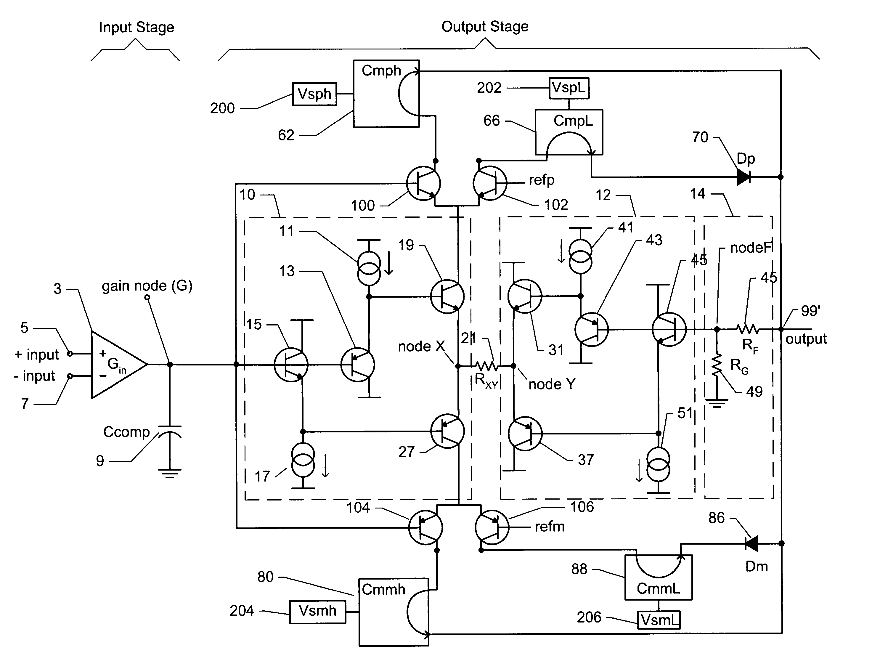
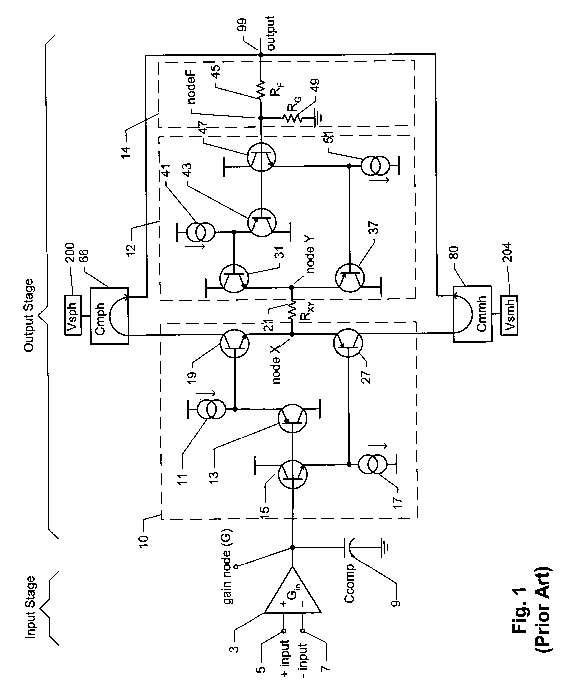
[0019]The present invention relates to Class-G amplifiers. The so-called Class-G amplifier approach uses two sets of power supplies, including a lower voltage supply (or supplies) which provides the majority of the output and quiescent currents, and a higher voltage supply (or supplies) which provides the output current only for the occasional signal peaks. The amplifier switches between supplies with signal demand. Prior to discussing Class-G amplifiers, it is useful to first describe a possible implementation of a Class-AB amplifier with reference to FIG. 1.

[0020]The Class-AB amplifier of FIG. 1 includes a differential input stage 3, which has a non-inverting input 5 and an inverting input 7. The output of the input stage is labeled gain node (G). A compensation capacitor 9 (Ccomp) is preferably connected between the gain node (G) and ground, to reduce and preferably eliminate oscillations at the gain node. Everything to the right of the input stage 3 can be considered an output s...


PUM


Abstract

An output stage for a Class-G amplifier includes four current mirrors, (CmpL) powered by a first low voltage supply (VspL), (Cmph) powered by a first high voltage supply (Vsph), (CmmL ) powered by a second low voltage supply (VsmL), and (Cmmh) powered by a second high voltage supply (Vsmh). The outputs of the current mirrors are connected together to form an output of the output stage. A buffer (10), whose input forms an input to the output stage, includes a first transistor (19) and a second transistor (27) connected in an emitter follower configuration, which are used to steer the buffer's output either through the first transistor (19) to a first switch (69) or through the second transistor (27) to a second switch (84). The first switch (69), which is controlled by a first comparator (68) connects a collector of the first transistor (19) to either the input to the first current mirror (CmpL) or the input to said second current mirror (Cmph). The second switch (84), which is controlled by a second comparator (82) connects a collector of the second transistor (27) to either the input to the third current mirror (CmmL) or the input to the fourth current mirror (Cmmh). This description is not intended to be a complete description of, or limit the scope of, the invention. Other features, aspects, and objects of the invention can be obtained from a review of the specification, the figures, and the claims.

Description

PRIORITY CLAIM[0001]This application claims priority under 35 U.S.C. 119(e) to U.S. Provisional Application No. 60 / 549,517, filed Mar. 2, 2004, entitled CLASS G-AMPLIFIERS, which is incorporated herein by reference.FIELD OF THE INVENTION[0002]Embodiments of the present invention relate to Class-G amplifiers.BACKGROUND[0003]Most amplifiers have push-pull output devices that are biased in a Class-AB manner. Such amplifiers draw a nominal quiescent current from the power supplies that must be at a voltage high enough to drive the largest output signal, even if the majority of the output signal is relatively low, with only occasional large peaks. For example, in the case of Digital Subscriber Line (DSL) signals, the majority of the signal is at a relative low level, with only occasional large output peaks. This results in the standard Class-AB output stage wasting about five times the delivered output power. Accordingly, Class-AB amplifiers are inefficient in that they waste a large amo...

Claims


Application Information

Patent Timeline
Patent Type & Authority Patents(United States)
IPC IPC(8): H03F3/18
CPCH03F3/21H03F1/025
Inventor HARVEY, BARRY
Owner ELANTEC SEMICON
Why Eureka
Try Eureka