
Impedance control in electrical connectors

a technology of electrical connectors and impedance control, applied in the direction of coupling contact members, connection contact member materials, coupling device connections, etc., can solve the problems of compromising signal integrity, limiting contact density (and therefore connector size), and unsatisfactory interference, etc., to achieve the effect of limiting the level of cross talk

Inactive Publication Date: 2006-01-03
FCI AMERICAS TECH LLC
View PDF90 Cites 142 Cited by
  • Summary
  • Abstract
  • Description
  • Claims
  • Application Information

AI Technical Summary

Benefits of technology

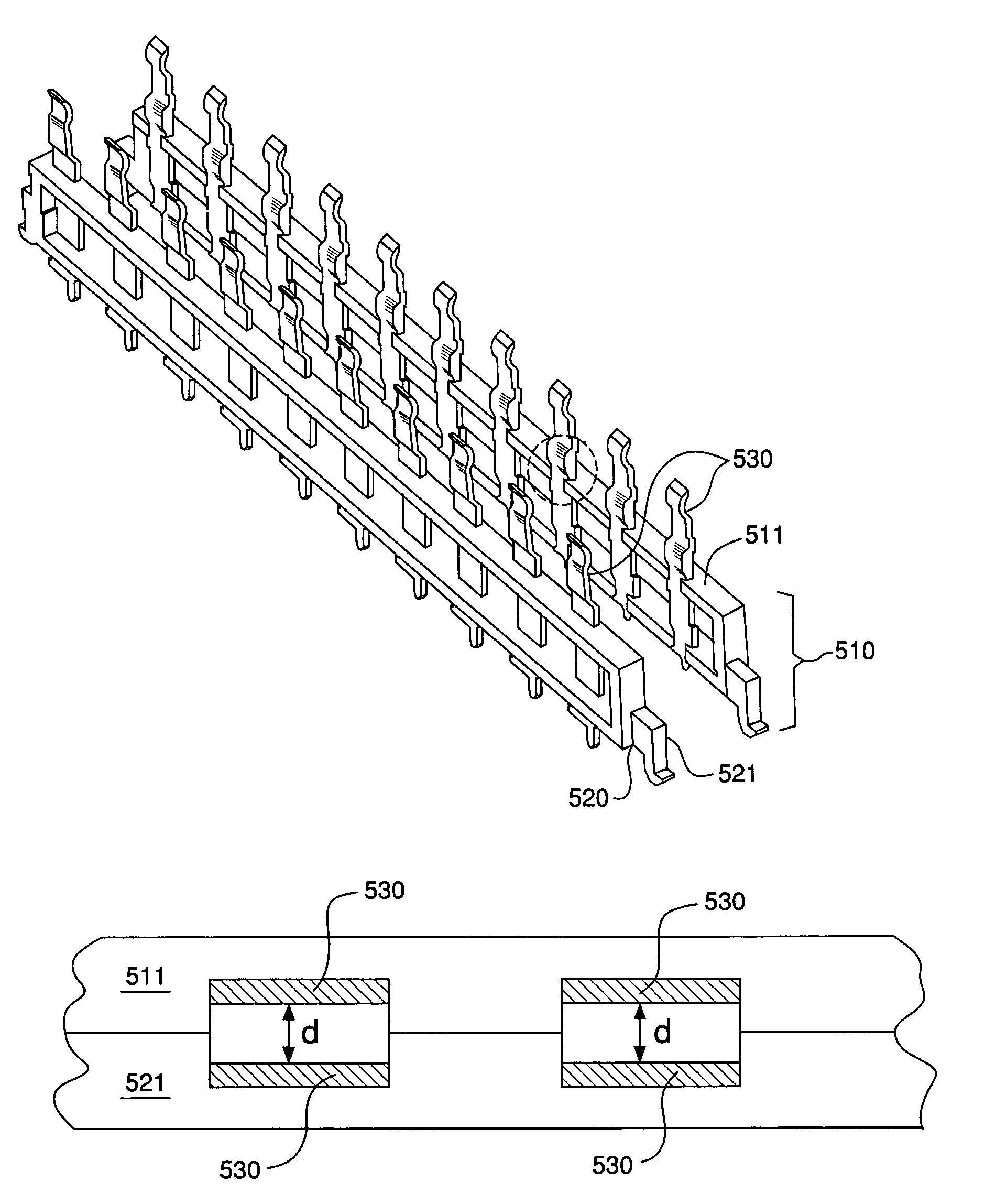
"The invention is a high-speed connector that reduces interference between signal pairs. It consists of multiple signal contact pairs, each with a gap between them. This gap limits the loss of signal and cross-talk between pairs. The connector may be made up of a header and receptacle leadframe assembly, each with an overmolded housing and contacts that extend through it. The leadframe assemblies are designed to maintain the width of the gap between contacts. This design eliminates the need for additional shields or ground contacts."

Problems solved by technology

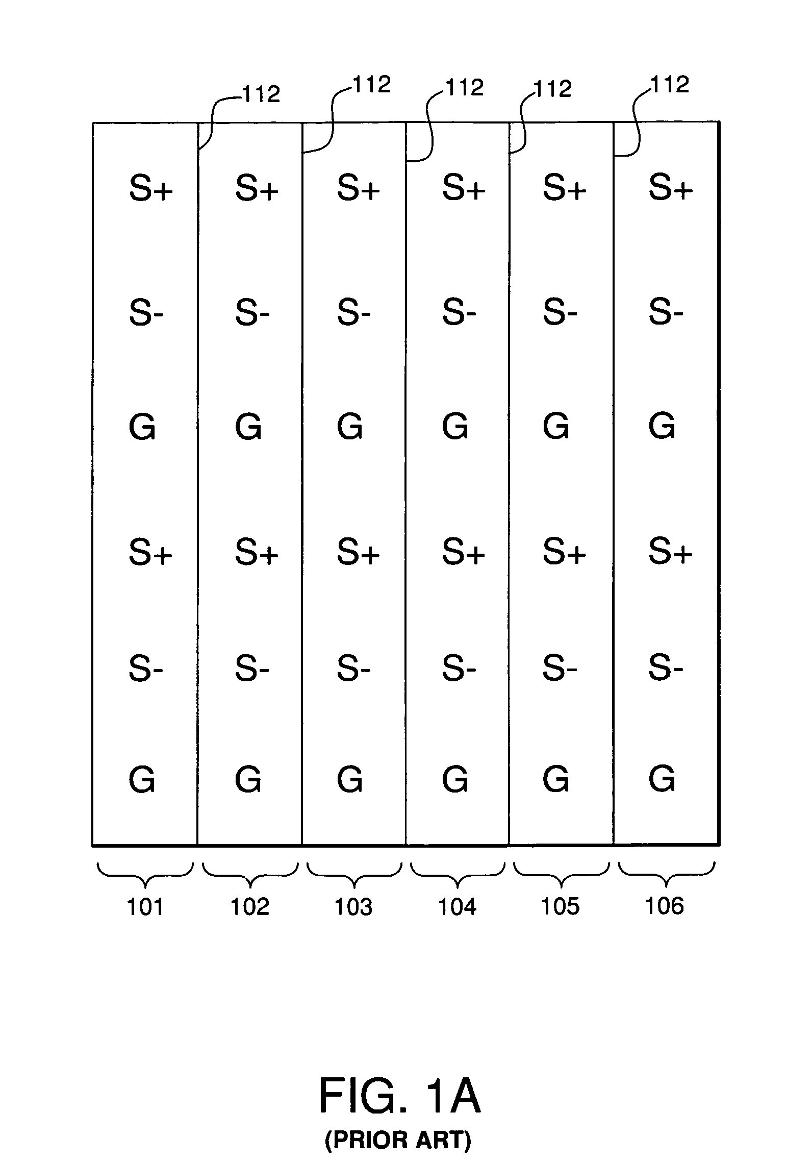
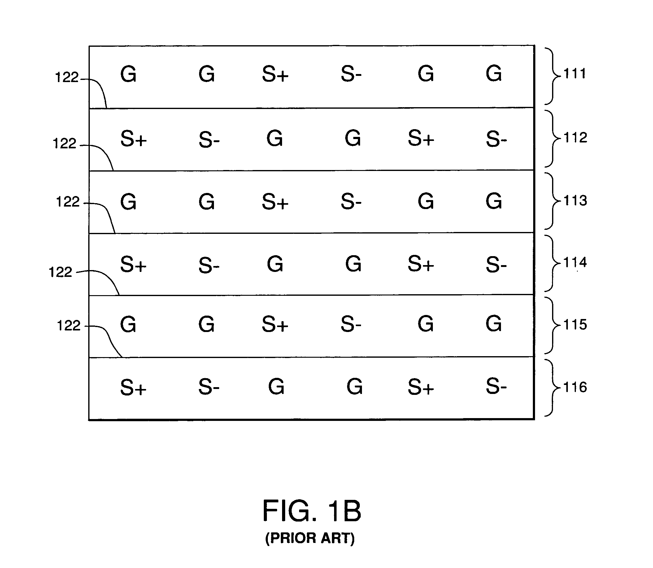
Often, the signal contacts are so closely spaced that undesirable interference, or “cross talk,” occurs between adjacent signal contacts.
Cross talk occurs when one signal contact induces electrical interference in an adjacent signal contact due to intermingling electrical fields, thereby compromising signal integrity.
Shields and ground contacts take up valuable space within the connector that could otherwise be used to provide additional signal contacts, and thus limit contact density (and, therefore, connector size).
Additionally, manufacturing and inserting such shields and ground contacts substantially increase the overall costs associated with manufacturing such connectors.
Another known disadvantage of shields is that they lower impedance.
Thus, to make the impedance high enough in a high contact density connector, the contacts would need to be so small that they would not be robust enough for many applications.
Furthermore, ground contacts can take up a large percentage of the available contacts in a connector, thus causing an increase in size and weight of the connector for a given number of differential signal pairs.

Method used


Image

  • Impedance control in electrical connectors
  • Impedance control in electrical connectors
  • Impedance control in electrical connectors

Examples


Embodiment Construction

[0021]The subject matter of the present invention is described with specificity to meet statutory requirements. However, the description itself is not intended to limit the scope of this patent. Rather, the inventors have contemplated that the claimed subject matter might also be embodied in other ways, to include different steps or elements similar to the ones described in this document, in conjunction with other present or future technologies. Moreover, certain terminology may be used in the following description for convenience only and should not be considered as limiting the invention in any way. For example, the terms “top,”“bottom,”“left,”“right,”“upper,” and “lower” designate directions in the figures to which reference is made. Likewise, the terms “inwardly” and “outwardly” designate directions toward and away from, respectively, the geometric center of the referenced object. The terminology includes the words above specifically mentioned, derivatives thereof, and words of ...


PUM


Abstract

The invention provides a high speed connector wherein differential signal pairs are arranged so as to limit the level of cross talk between adjacent differential signal pairs. The connector comprises lead frame assembly having a pair of overmolded lead frame housings. Each lead frame housing has a respective signal contact extending therethrough. The lead frame housings may be operatively coupled such that the signal contacts form a broadside-coupled differential signal pair. The contacts may be separated by a gap having a gap width that enables insertion loss and cross talk between signal pairs to be limited.

Description

CROSS REFERENCE TO RELATED APPLICATIONS[0001]This application is a continuation-in-part of co-pending U.S. patent application Ser. No. 10 / 294,966, filed Nov. 14, 2002, which is a continuation-in-part of U.S. patent application Ser. No. 09 / 990,794, filed Nov. 14, 2001, now U.S. Pat. Nos. 6,692,272, and 10 / 155,786, filed May 24, 2002, now U.S. Pat. No. 6,652,318. The contents of each of the above-referenced U.S. patents and patent applications is herein incorporated by reference in its entirety.FIELD OF THE INVENTION[0002]Generally, the invention relates to the field of electrical connectors. More particularly, the invention relates to an impedance-controlled insert molded leadframe assembly (“IMLA”) in a “split” configuration.BACKGROUND OF THE INVENTION[0003]Electrical connectors provide signal connections between electronic devices using signal contacts. Often, the signal contacts are so closely spaced that undesirable interference, or “cross talk,” occurs between adjacent signal co...

Claims


Application Information

Patent Timeline
Patent Type & Authority Patents(United States)
IPC IPC(8): H01R12/00H01R4/66H01R13/502H01R13/646H01R13/648
CPCH01R13/26H01R13/6471H01R13/6477H01R24/44H01R13/00H01R13/648
Inventor RAISTRICK, ALANSHUEY, JOSEPH B.
Owner FCI AMERICAS TECH LLC
Learn More