
Multi-point lock assembly

Inactive Publication Date: 2006-01-03
ROTO FASCO CANADA
View PDF19 Cites 33 Cited by
  • Summary
  • Abstract
  • Description
  • Claims
  • Application Information

AI Technical Summary

Benefits of technology

[0005]The present invention provides a multi-point lock assembly for sliding closures, such as patio doors, which eliminates the problems associated with the prior art devices as described above.
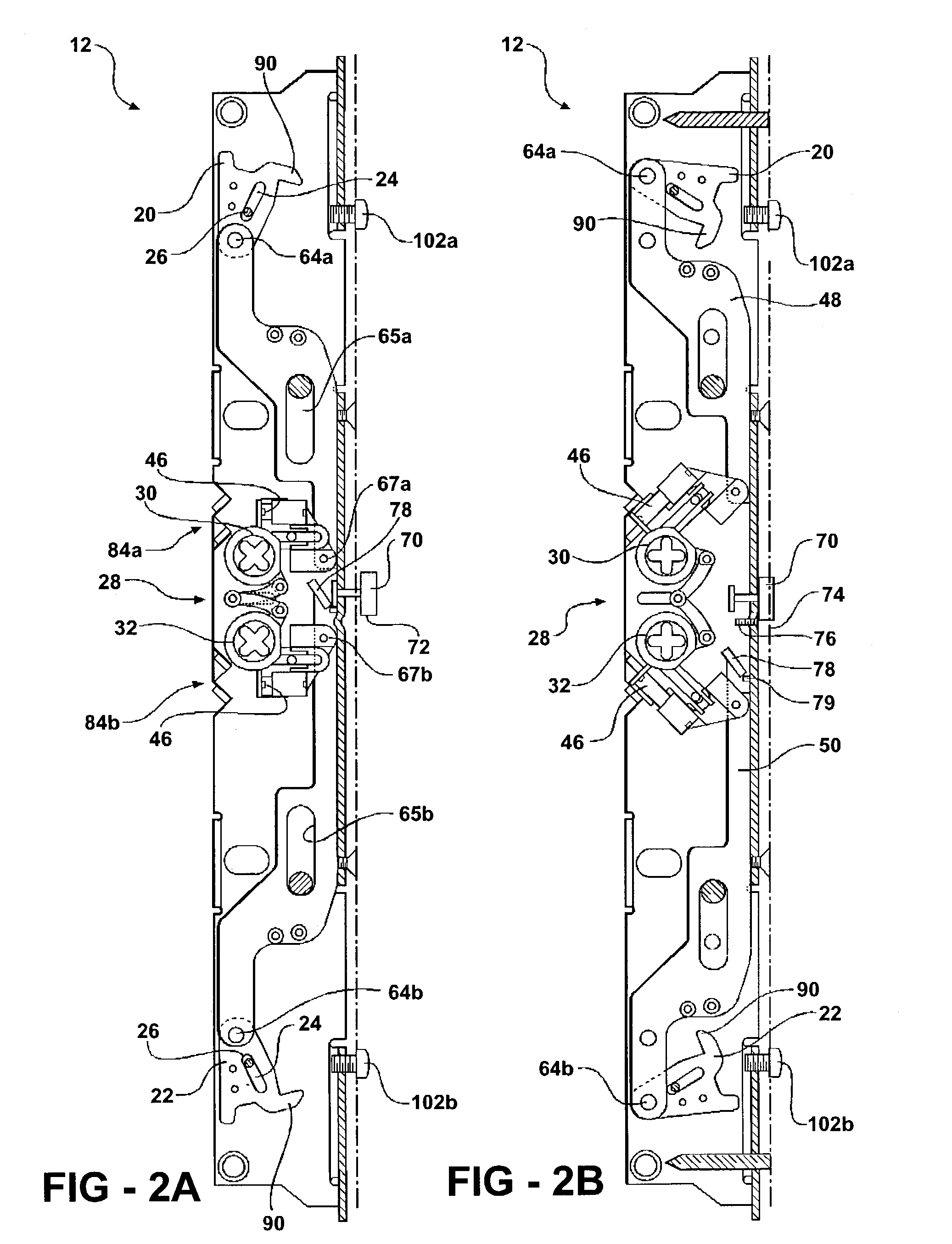
[0014]An anti-slam feature for the multi-point lock assembly is provided for preventing the hooks and latches from rotating into the locking position when the latch unit, located on the moveable member, is displaced from an engaged position relative to the keeper-unit which is located in the stationary member. A release button, located in the latch unit, is engaged by a stop-rod, located in the keeper-unit, when the moveable member engages the stationary member during closing. Once the release button is depressed, the actuator can be be turned and the lock mechanism is free to complete the locking sequence.

Problems solved by technology

A problem associated with this conventional configuration is that because the thumb turn can be operated in any door position, the hooks can be extended prior to the door being closed.
If the door is forcibly closed with the hooks extended, damage can be caused to the hooks, to the keeper plate, or to both.
This method of preventing damage to the lock mechanism is more expensive due to the complexity of the design.

Method used


Image

  • Multi-point lock assembly
  • Multi-point lock assembly
  • Multi-point lock assembly

Examples


first embodiment

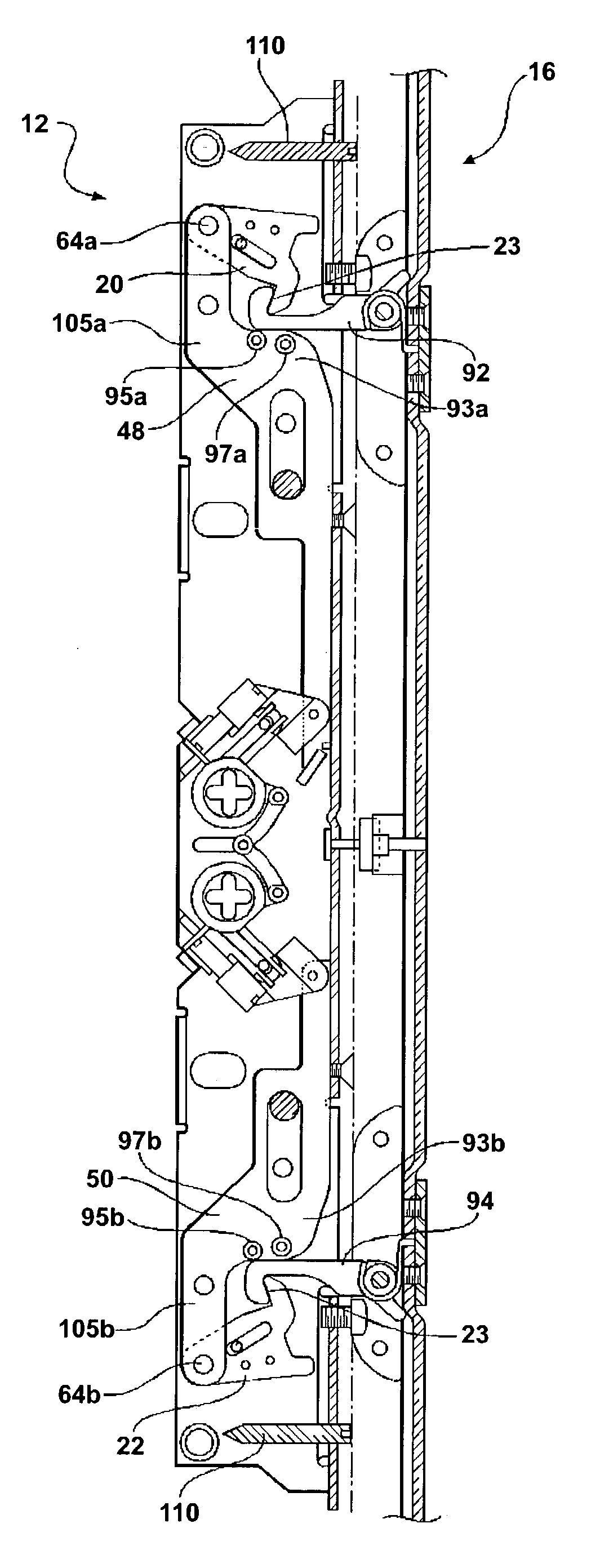
[0046]Referring now to FIG. 7, the keeper unit 16 is shown therein. Adjustable clips 118a, 118b are operably associated with each hook 92, 94 for positioning the hooks 92, 94 at a predetermined location such that the hooks 92, 94 will engage the latch unit 12 at the correct spacial position relative to the keeper unit 16 when the moveable member 14 is in the closed position. Each adjustable clip 118a, 118b has two sides 120a, 120b with a mounting member 122a, 122b extending therebetween for connecting the adjustable clips 118a, 118b to a keeper plate 124 via fasteners 121a, 121b. The keeper plate 124 has a plurality of longitudinally extended ribs 126 for increasing the strength of the keeper plate 124 and for forming a counter-bore area 128 for the heads of the threaded fasteners (not shown) to lie therein for connecting the keeper plate to the stationary member 18.

[0047]Each adjustable clip 118a, 118b includes an upper pair of apertures 125a, 125b and a lower pair of apertures 129...

second embodiment

[0049]Referring now to FIG. 8, the keeper unit 16 is shown therein. A substantially U-shaped channel keeper 134 having a pivot pin 135 for attaching each hook 92, 94 within the U-shaped recess 136. The channel keeper 134 operable for positioning the hooks 92, 94 at a predetermined location relative to the latch unit 12. The channel keeper 134 has a plurality of apertures 138 for fastening members (not shown) to engage therethrough and fasten the channel keeper 134 to the stationary member 18. A plurality of substantially U-shaped filler members 140 are positioned in the U-shaped channel keeper 134 for covering the U-shaped recess 136 adjacent to the hooks 92, 94. At least one protruding element 142 extends from each side of each U-shaped filler member 140 for releasibly snap-locking with apertures 144 formed in the U-shaped channel keeper 134. The U-shaped channel keeper 134 is typically made of a metal material and the filler members 140 are typically made of a plastic, however, su...


PUM


Abstract

A multi-point latch assembly having a locking unit operably positioned in a closure member such as a door or window. The latch unit has a pair of latches with slots formed therein permitting the latches to simultaneously slide and pivotally engage a stationary pin. A keeper unit is operably positioned in a stationary member such as a door jam in a wall or a window sash. The keeper unit has a pair of pivotally movable hooks for selectively engaging the pair of latches in the latch unit. The latch unit has an actuator unit located internal to the latch unit for causing the hooks and latches to engage one another. The closure member is prevented from moving relative to the stationary member without first disengaging the hooks and latches from one another. The multi-point latch assembly has a stop rod located in the keeper unit. A release button located on the latch unit engages the stop rod when the closure member is closed. The latch unit is incapable of actuating the hooks and latches until the release button contacts the stop rod when the closure member is in a closed position relative to the stationary member.

Description

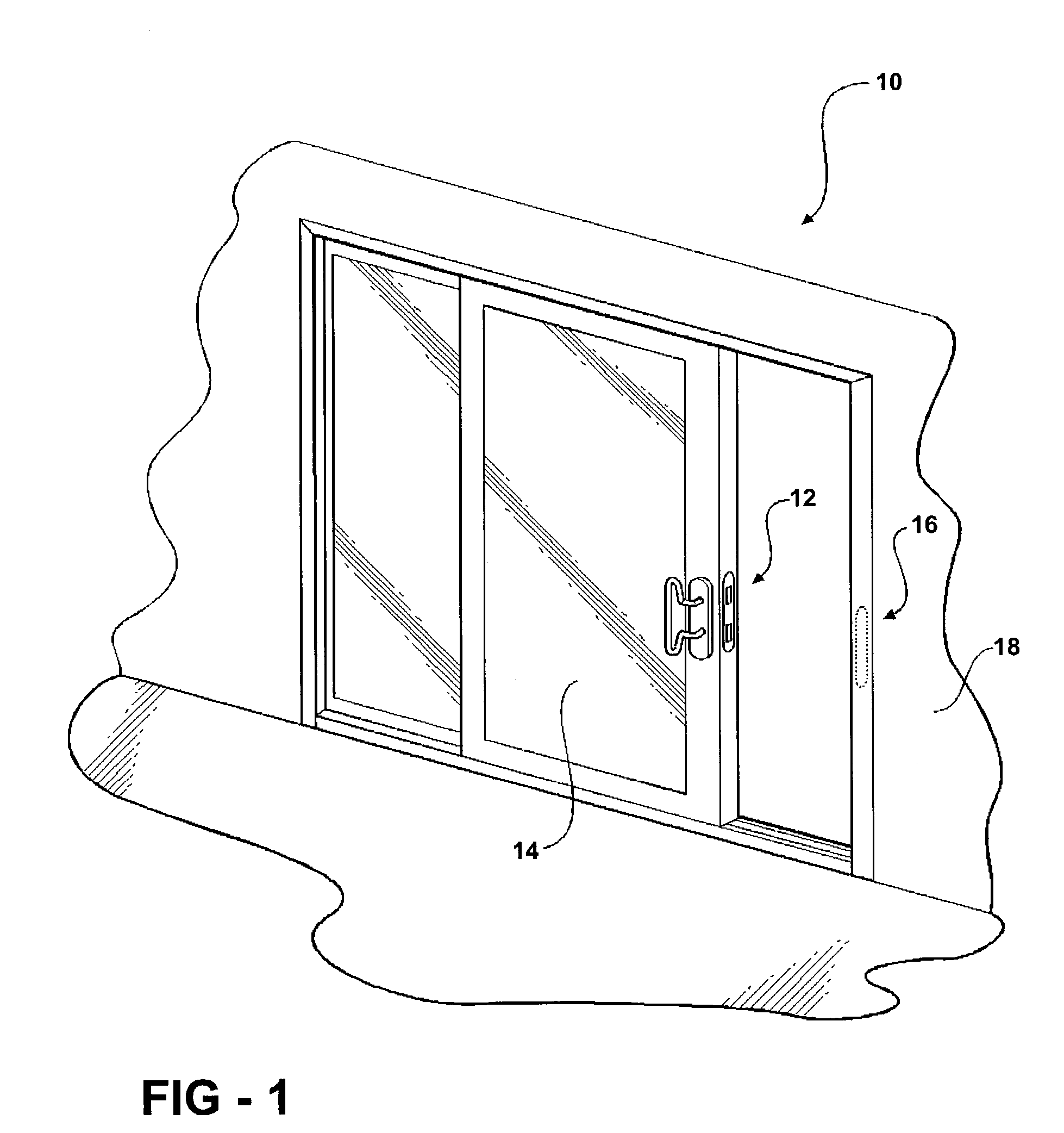
FIELD OF THE INVENTION[0001]The present invention relates to a multi-point lock assembly having locking hooks positioned in the stationary keeper of a door unit.BACKGROUND OF THE INVENTION[0002]In a typical sliding door installation, a lock unit having one or more hooked locking members is mounted into a movable door. A keeper unit is mounted into a stationary door opening member or jamb. The door is closed by bringing the lead edge into contact with the jamb and then locked by rotating a thumb turn to cause the locking hooks to extend out from the edge of the door and into the slots in the keeper plate.[0003]A problem associated with this conventional configuration is that because the thumb turn can be operated in any door position, the hooks can be extended prior to the door being closed. If the door is forcibly closed with the hooks extended, damage can be caused to the hooks, to the keeper plate, or to both.[0004]One way to solve this problem is to use hooks which collapse when ...

Claims


Application Information

Patent Timeline
IPC IPC(8): E05C5/00E05B63/18E05B63/24E05B65/08
CPCE05B65/0858E05B63/24E05B63/185Y10S292/53Y10T292/0828Y10T292/0887
Inventor DENYS, ANDRE
Owner ROTO FASCO CANADA
Learn More