DC-DC converter with noise spreading to meet spectral mask requirements

a technology of noise spreading and dc converter, which is applied in the direction of amplitude demodulation, line-fault/interference reduction, pulse technique, etc., can solve the problems of interfering with other electronic devices such as computers or televisions, communication may interfere with other electronic devices, and various communication protocols used by mobile terminals may impose more restrictive limitations, so as to achieve the effect of occupying less spa

Inactive Publication Date: 2005-12-27
QORVO US INC
View PDF39 Cites 24 Cited by
  • Summary
  • Abstract
  • Description
  • Claims
  • Application Information

AI Technical Summary

Benefits of technology

[0007]The present invention minimizes spurious emissions by spreading the frequency at which a variable oscillator in a switching power supply operates and flattening the spectrum of the spurious emissions. Specifically, the present invention represents a modification to a switching power supply that can be used in a myriad of mobile terminals, although it is especially well suited for use with Global System for Mobile Communications (GSM) compatible mobile terminals.
[0012]In a second embodiment, a single DAC and a single capacitor are used with current mirrors to reflect the current into the current source and current sink. This embodiment uses more current than the first embodiment, but has the advantage of taking up less space.

Problems solved by technology

An unfortunate side effect of the convenience of this wireless communication is that the signal-carrying electromagnetic radiation that forms the backbone of the communication may interfere with other electronic devices.
While interfering with other electronic devices like a computer or television is problematic, it is also possible for multiple mobile terminals operating in proximity to one another to have cross channel EMI.
On top of the FCC emissions rules, the various communication protocols used by mobile terminals may impose more restrictive limitations with specific attention paid to side band transmission levels.
If the DC—DC converter is used to provide a supply voltage (Vcc) to a saturated power amplifier, this ripple may mix with the radio frequency carrier to generate spurious side band signals.
This substitution avoids the ripple issues, but does so at the expense of decreased efficiency and shorter battery life.

Method used


Image

  • DC-DC converter with noise spreading to meet spectral mask requirements
  • DC-DC converter with noise spreading to meet spectral mask requirements
  • DC-DC converter with noise spreading to meet spectral mask requirements

Examples


first embodiment

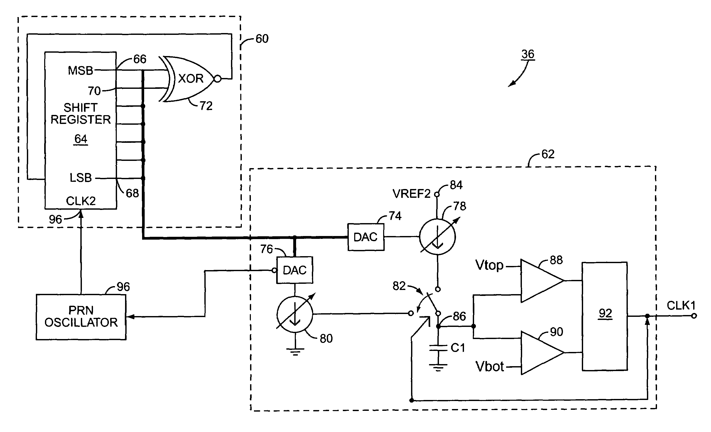
[0041]the oscillator 36 of the present invention is illustrated in FIG. 6. Similarly to the oscillator 36 of FIG. 4, the oscillator 36 includes the pseudo random number generator 60 and the clock generation circuit 62. The pseudo random number generator 60 includes the seven bit shift register 64 and the exclusive OR (XOR) gate 72 operating such that the shift register 64 counts in a pseudo random fashion and thus outputs a pseudo random number. Other pseudo random number generators 60 could also be used if needed or desired. Likewise, the number of bits in the shift register may vary from embodiment to embodiment as needed or desired.

[0042]The outputs of the pseudo random number generator 60 are collectively sent to the clock generation circuit 62. The DACs 74, 76 translate the digital signal from the pseudo random number generator 60 into an analog current control signal that controls the variable current sources 78, 80 respectively. The current sources 78, 80 are selectively conn...

second embodiment

[0046]the oscillator 36 of the present invention is illustrated in FIG. 7. The PNG 60 outputs a pseudo random number to a DAC 250 that in turn controls a variable current source 252 via an analog current control signal and further controls the frequency of the PRN oscillator 96 via an oscillator control signal. The current control signal is from a non-inverting output of the DAC 250, and the oscillator control signal is from an inverting output of the DAC 250. Therefore, the oscillator control signal is the inverse of the current control signal provided to the variable current source 252. Accordingly, when the clock generation circuitry 62 is operating at the high end of its frequency range, the PRN oscillator 96 is operating at the low end of its frequency range, and vice versa. Thus, the oscillator 36 spends more time generating higher frequencies than lower frequencies. In doing so, the oscillator 36 operates to flatten the spurious response illustrated in FIG. 5.

[0047]In operati...


PUM


Abstract

A DC—DC converter includes a variable frequency oscillator, a control system and a power train. The DC—DC converter is well suited for use in a cell phone. The control system uses the output of the oscillator to control the power train. The oscillator varies its frequency as a function of a pseudo random number generator, thereby reducing electromagnetic interference caused by ripple in the output of the DC—DC converter.

Description

FIELD OF THE INVENTION[0001]The present invention is related to a DC—DC converter and specifically a switching regulator DC—DC converter with an oscillator whose frequency changes to reduce electromagnetic interference.BACKGROUND OF THE INVENTION[0002]Mobile terminals such as cellular phones have become ubiquitous in modern society. Mobile terminals rely on sending an electromagnetic signal through the air to a base station and receiving electromagnetic signals through the air from the base station. An unfortunate side effect of the convenience of this wireless communication is that the signal-carrying electromagnetic radiation that forms the backbone of the communication may interfere with other electronic devices. This phenomenon is known as electromagnetic interference (EMI) or electromagnetic compatibility (EMC).[0003]While interfering with other electronic devices like a computer or television is problematic, it is also possible for multiple mobile terminals operating in proxim...

Claims


Application Information

Patent Timeline
IPC IPC(8): H02M3/156H03K3/84
CPCH02M1/12H02M3/156
Inventor DENING, DAVIDREED, DAVID E.SCOTT, BAKER
Owner QORVO US INC
Why Eureka
Try Eureka