Autofocus control apparatus and method
a technology of autofocus control and control apparatus, which is applied in the direction of radio frequency control devices, instruments, television systems, etc., can solve the problems of increasing costs and inability to perform high-speed and high-precision autofocus operations, and achieves low cost and high accuracy of autofocus functions.
- Summary
- Abstract
- Description
- Claims
- Application Information
AI Technical Summary
Benefits of technology
Problems solved by technology
Method used
Image

Examples
first embodiment
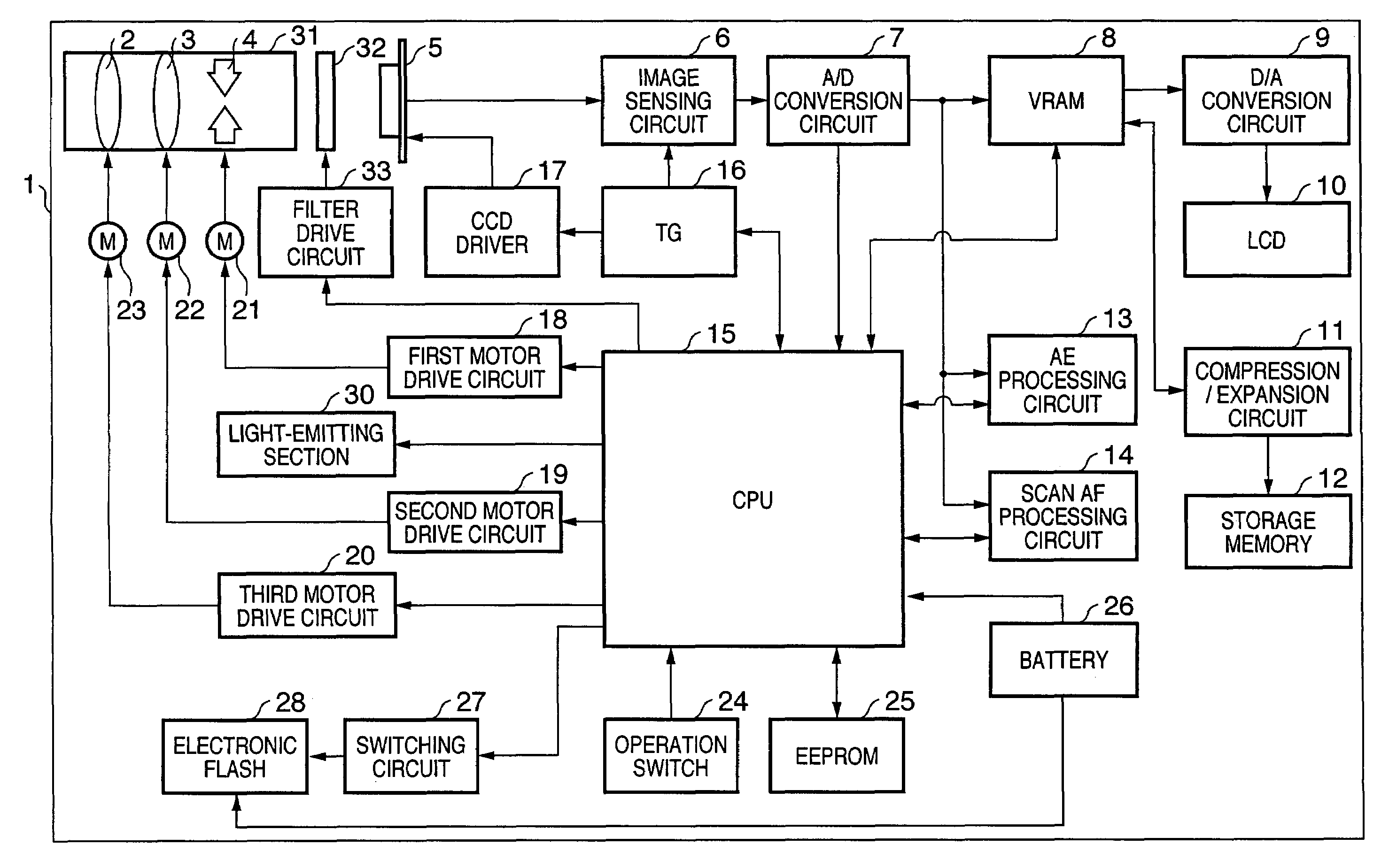
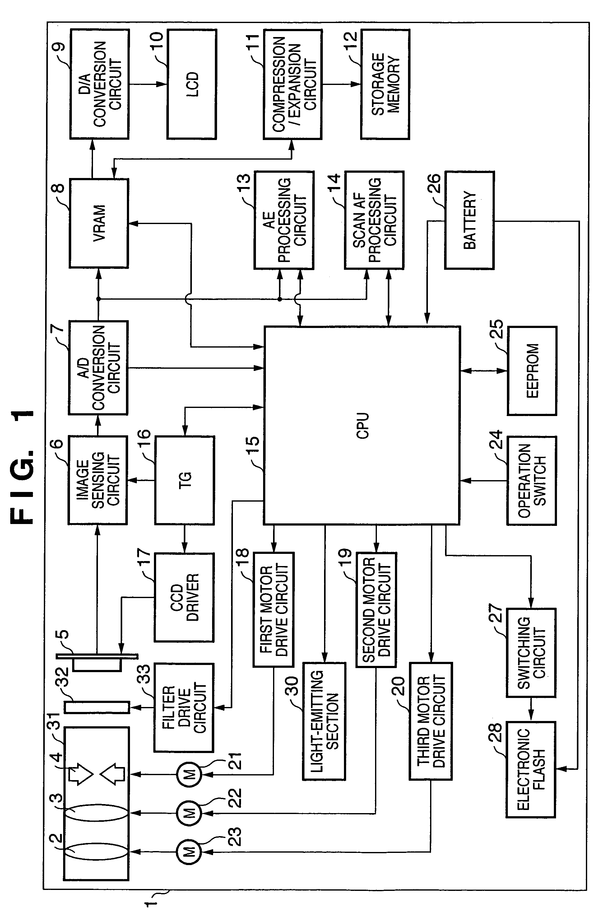
[0027]FIG. 1 is a block diagram showing an example of a schematic structure of an image sensing apparatus according to a first embodiment of the present invention. The image sensing apparatus includes, for example, a digital still camera and a digital video camera but is not limited to these cameras. It is possible to apply the present invention to any image sensing apparatus as long as the image sensing apparatus acquires an incident optical image as an electrical image by photoelectric conversion using a solid-state image sensing device, such as an area sensor, whose pixels are arranged two-dimensionally.
[0028]In FIG. 1, reference numeral 1 denotes an image sensing apparatus; 2, a group of zoom lenses; 3, a group of focus lenses; 4, a stop serving as a light amount adjusting unit and an exposure unit that controls an amount of light beams transmitted through an image sensing optical system including the group of zoom lenses 2, the group of focus lenses 3, and the like; 31, a lens-...
second embodiment
[0094]Next, a second embodiment of the present invention will be described.
[0095]A basic constitution of an image sensing apparatus and its basic operation procedure according to the second embodiment are the same as the first embodiment. However, a method of detecting an object in the active AF is different from the method that is described with reference to FIGS. 4 and 5 in the first embodiment. Thus, the method will be described.
[0096]In the active AF in the second embodiment, detection of an object is performed in a plurality of rows, and a most appropriate object is selected out of obtained objects. In addition, as in the first embodiment, only pixels corresponding to red of a color filter having highest sensitivity to an infrared ray are used.
[0097]Processing for extracting a reflected image and calculating a center of gravity thereof, which is performed in step S28 of FIG. 3, will be hereinafter described with reference to FIGS. 9 and 10. Here, an object with a relatively hig...
third embodiment
[0120]Next, a third embodiment of the present invention will be described.
[0121]A basis constitution of an image sensing apparatus and its basic operation procedure according to the third embodiment are the same as the first embodiment. However, a method of detecting an object in the active AF is different from the method that is described with reference to FIG. 4 in the first embodiment. Thus, the method will be described.
[0122]In the active AF in the third embodiment, detection of an object is performed using differential data of one line, and a most appropriate object is selected out of obtained objects.
[0123]Processing for extracting a reflected image and calculating a center of gravity thereof, which is performed in step S28 of FIG. 3, will be hereinafter described with reference to FIGS. 11 and 5. Here, an object with a relatively high luminance having steep leading and trailing edges is extracted, and a center of gravity of the extracted object is found.
[0124]First, in step S...
PUM
 Abstract
Description
Claims
Application Information
 - R&D
- Intellectual Property
- Life Sciences
- Materials
- Tech Scout
- Unparalleled Data Quality
- Higher Quality Content
- 60% Fewer Hallucinations
Browse by: Latest US Patents, China's latest patents, Technical Efficacy Thesaurus, Application Domain, Technology Topic, Popular Technical Reports.
© 2025 PatSnap. All rights reserved.Legal|Privacy policy|Modern Slavery Act Transparency Statement|Sitemap|About US| Contact US: help@patsnap.com