
Space saving fin deployment system for munitions and missiles

a technology for deploying systems and missiles, which is applied in the field of space saving fin deployment systems for munitions and missiles, can solve the problems of unsatisfactory maintenance of high complexity of missile and munitions systems, and inability to deploy systems for 2.75 inch rockets, etc., and achieves good roll control authority, increase the onboard towing capacity of electronic packaging, and substantial space saving

Inactive Publication Date: 2005-12-27
UNITED STATES OF AMERICA THE AS REPRESENTED BY THE SEC OF THE ARMY
View PDF13 Cites 29 Cited by
  • Summary
  • Abstract
  • Description
  • Claims
  • Application Information

AI Technical Summary

Benefits of technology

[0011]It is a feature of the present invention to provide a new design methodology for fin deployment system for missiles and munitions that substantially reduces the volume taken up by the fin deployment system within a projectile body. Further, it is a novelty of the present invention to provide a new method for deploying and activating straight flat fins for roll control authority. In summary, the new design method for a space-saving straight fin deployment system employs a number of novel design features as follows:
[0012]1. A wrap-around fin concept generates space-savings within a projectile body whereby the fins are arranged in a wrapped configuration around a boomtail structure.
[0014]3. The system eliminates mechanical means of deploying the wrapped fins, no springs are needed to deploy the fins. Physics of system generates equal deploying fins.
[0015]The space-saving fin deployment system affords advantages over a conventional fin deployment system in achieving substantial space savings for increasing the onboard towing capacity of electronic packaging or lethality in the missiles and munitions systems, while at the same time providing a good roll control authority during flight by enabling a straight fin deployment resulting from the use of super-elastic materials. In some particular applications, the space savings could be reduced by a factor of two as compared to a conventional design.

Problems solved by technology

Missiles and munitions are highly complex systems generally used for deploying projectiles capable of high-speed and long-range maneuvers to deliver lethality to a target or to intercept an incoming threat.
In practice, problems with this conventional fin deployment system have been encountered whereby the deployed fins have curved surfaces upon deploying from their housing, the fin itself is shaped to the profile of the missile projectile for a semi-circular fin shape.
Roll control authority is needed for guided missile projectile systems; therefore the deployment system used by the 2.75 inch rocket is not viable.
Thus, it is realized that the current attempts to provide a fin deployment systems that can achieve a considerable projectile volume savings while maintaining a good roll control authority heretofore remains unfulfilled.

Method used


Image

  • Space saving fin deployment system for munitions and missiles
  • Space saving fin deployment system for munitions and missiles
  • Space saving fin deployment system for munitions and missiles

Examples


Embodiment Construction

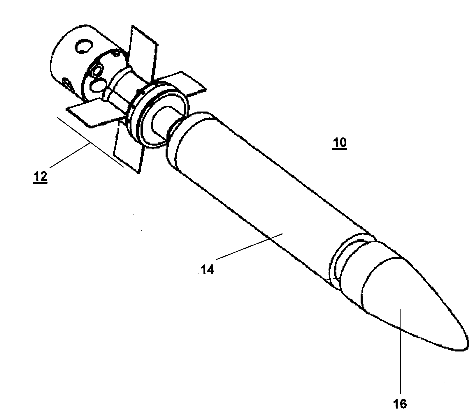
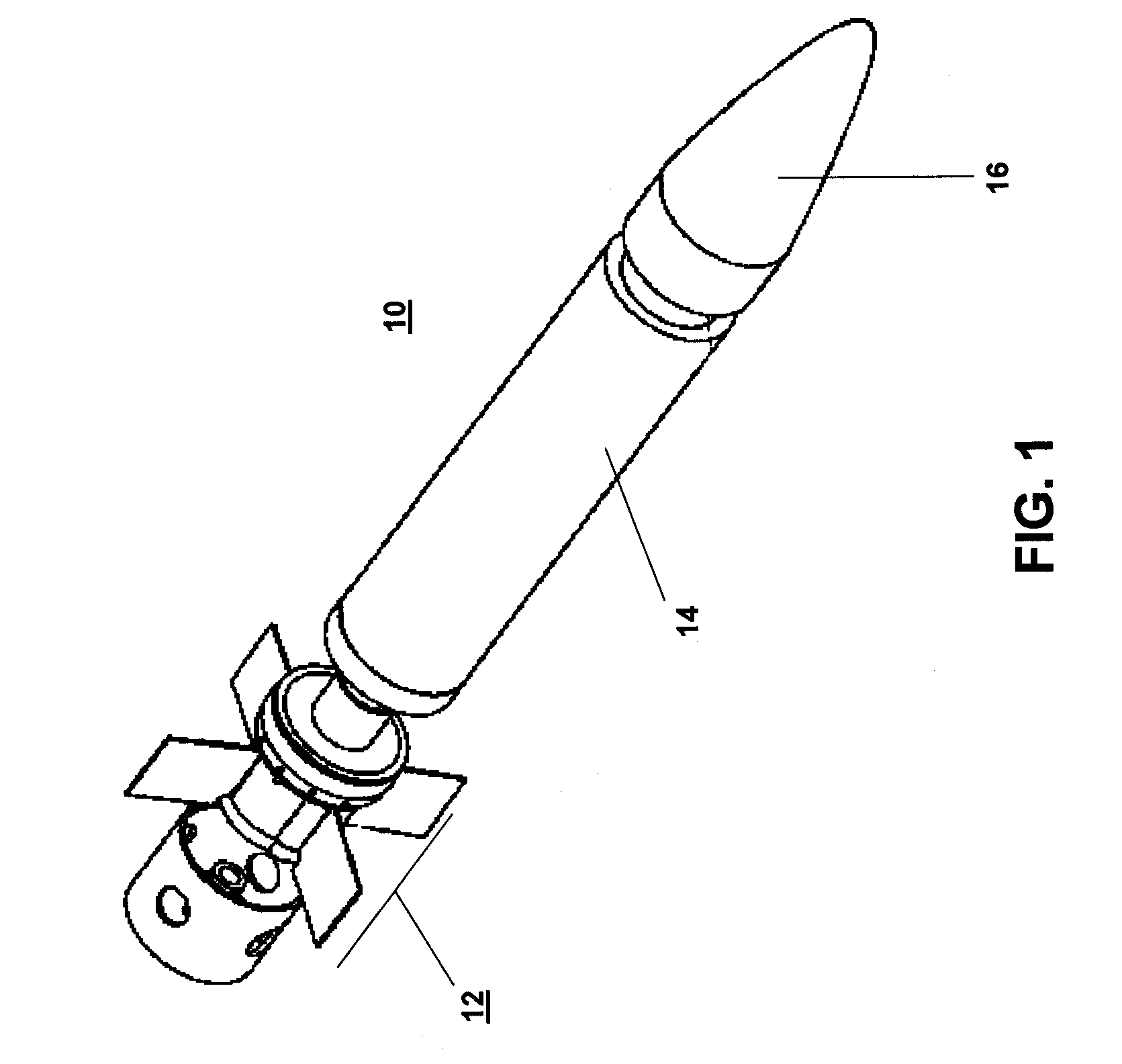
[0028]FIG. 1 illustrates a missile or munitions system 10 incorporating a space-saving fin deployment system 12 made according to the present invention. An exemplary munitions system 10 may be based upon a smart cargo concept that includes a 105-mm tank munitions used in the U.S. Armed Forces. The munitions system 10 is generally comprised of a number of major components; namely: a projectile body 14, a nose cone 16, and a preferred embodiment of the space-saving deployment system 12 that constitutes a novelty of the present invention. Each of these major components is further described as follows:

[0029]The projectile body 14 is generally made of a thin steel shell having a cylindrical shape. The interior volume of the projectile body 14 typically contains flammable propellant charges that provide a thrust force upon ignition to propel the munitions system 10 forward during flight. In addition, the interior volume also houses electronics packages such as guidance and control or leth...


PUM


Abstract

A fin deployment system for missiles and munitions that deploys and activates straight flat fins for roll control authority. The fin deployment system employs numerous design features, among which are the following: A wrap-around fin concept generates space-savings within a projectile body whereby the fins are arranged in a wrapped configuration around a boomtail structure. The fins may be constructed of a super-elastic material; the system eliminates mechanical means of deploying the wrapped fins, eliminating the need for springs to deploy the fins. The fin deployment achieves substantial space savings for increasing the onboard towing capacity of electronic packaging or lethality in the missiles and munitions systems, while at the same time providing a good roll control authority during flight by enabling a straight fin deployment resulting from the use of super-elastic materials.

Description

CROSS REFERENCE TO RELATED APPLICATIONS[0001]This application claims benefit under 35 USC 199(e) of provisional application 60 / 320,144, filed Apr. 25, 2003, the entire file wrapper contents of which provisional application are herein incorporated by reference as though fully set forth at length.FEDERAL RESEARCH STATEMENT[0002]The inventions described herein may be manufactured, used and licensed by or for the U.S. Government for U.S. Government purposes.BACKGROUND OF INVENTION[0003]1. Field of the Invention[0004]The present invention relates in general to the field of Missiles and Munitions used by the Armed Forces, and it particularly relates to a new design method for a fin deployment system that enables a substantial reduction in the volume of munitions as compared to those employing conventional fin deployment systems. More specifically, the present invention incorporates a novel wrap-around fin concept that is capable of achieving a straight fin deployment which is necessary in...

Claims


Application Information

Patent Timeline
Patent Type & Authority Patents(United States)
IPC IPC(8): F42B10/00F42B10/16
CPCF42B10/16
Inventor SCHEPER, ERICVELLA, ANTHONYMAURIZI, DAVEMOLINA, ANDREW
Owner UNITED STATES OF AMERICA THE AS REPRESENTED BY THE SEC OF THE ARMY
Learn More