
Retrofit module for adding a plasticizing and injection unit to an injection molding machine, and injection molding machine with added retrofit module

a technology of retrofitting and injection molding machine, which is applied in the field of injection molding machine, can solve the problems of inconvenient retrofitting of added plasticizing and injection units, lack of room, and insufficient ceiling height, and achieves the effects of saving space, improving efficiency, and improving efficiency

Inactive Publication Date: 2006-04-13
DEMAG ERGOTECH GMBH
View PDF3 Cites 2 Cited by
  • Summary
  • Abstract
  • Description
  • Claims
  • Application Information

AI Technical Summary

Benefits of technology

[0010] By constructing the injection molding machine in accordance with the present invention, the need for an additional nozzle orifice in the platen is eliminated so that no modifications of the platen are required. The construction of the nozzle assembly to allow docking of both plasticizing and injection units enables their operation independently from one another. The required installation space becomes smaller as both injection units are placed on one side of the platen, suitably the fixed platen, of the injection molding machine and are able to communicate via a common nozzle assembly with an injection mold of the injection molding machine. As the plasticizing and injection units are preferably positioned on the mold-distal side of the platen, the mold is easily accessible. Robots can thus be utilized for depositing inserts or for removing finished injection-molded products. An injection molding machine according to the present invention is very compact and requires less space than before. In particular, an excessive vertical extension can be avoided. Also the need for an additional machine bed, typically used when add-on units of the L version is involved which require must space to the side, is eliminated, and is applicable for use in two-component injection molding. Suitably, the plasticizing and injection units operate according to the so-called screw-piston principle, i.e. the screw of each plasticizing and injection unit assumes plasticizing as well as injection functions.
[0033] A standard injection molding machine which has been retrofitted with a further plasticizing and injection unit as well as a retrofit module with a plasticizing and injection unit for adding to an injection molding machine are very compact and space saving, whereby the retrofit module permits addition of a plasticizing and injection unit to a standard injection molding machine in a simple manner, without modification of the standard injection molding machine. Compared to conventional L and V constructions, the retrofit module according to the present invention results in substantial space saving and is flexible as well as enables rapid change-over times.

Problems solved by technology

A problem of the V configuration is the need for a relatively high ceiling of the room in order to provide sufficient clearance for movement of the injection unit away from the injection mold, when the additional injection unit is attached above the injection molding machine, so as to be able to remove injection-molded articles.
Oftentimes, the room lacks, however, sufficient ceiling height so that a retrofit according to the V configuration is possible only for very small add-on units or not possible at all.
These added plasticizing and injection units are not suitable for retrofitting as a consequence of their securement to the lower plasticizing and injection unit and the need to configure the platen for passage of a further plastic component.
Retrofitting becomes thus extremely difficult, requiring a replacement of the platen for example.

Method used


Image

  • Retrofit module for adding a plasticizing and injection unit to an injection molding machine, and injection molding machine with added retrofit module
  • Retrofit module for adding a plasticizing and injection unit to an injection molding machine, and injection molding machine with added retrofit module
  • Retrofit module for adding a plasticizing and injection unit to an injection molding machine, and injection molding machine with added retrofit module

Examples


Embodiment Construction

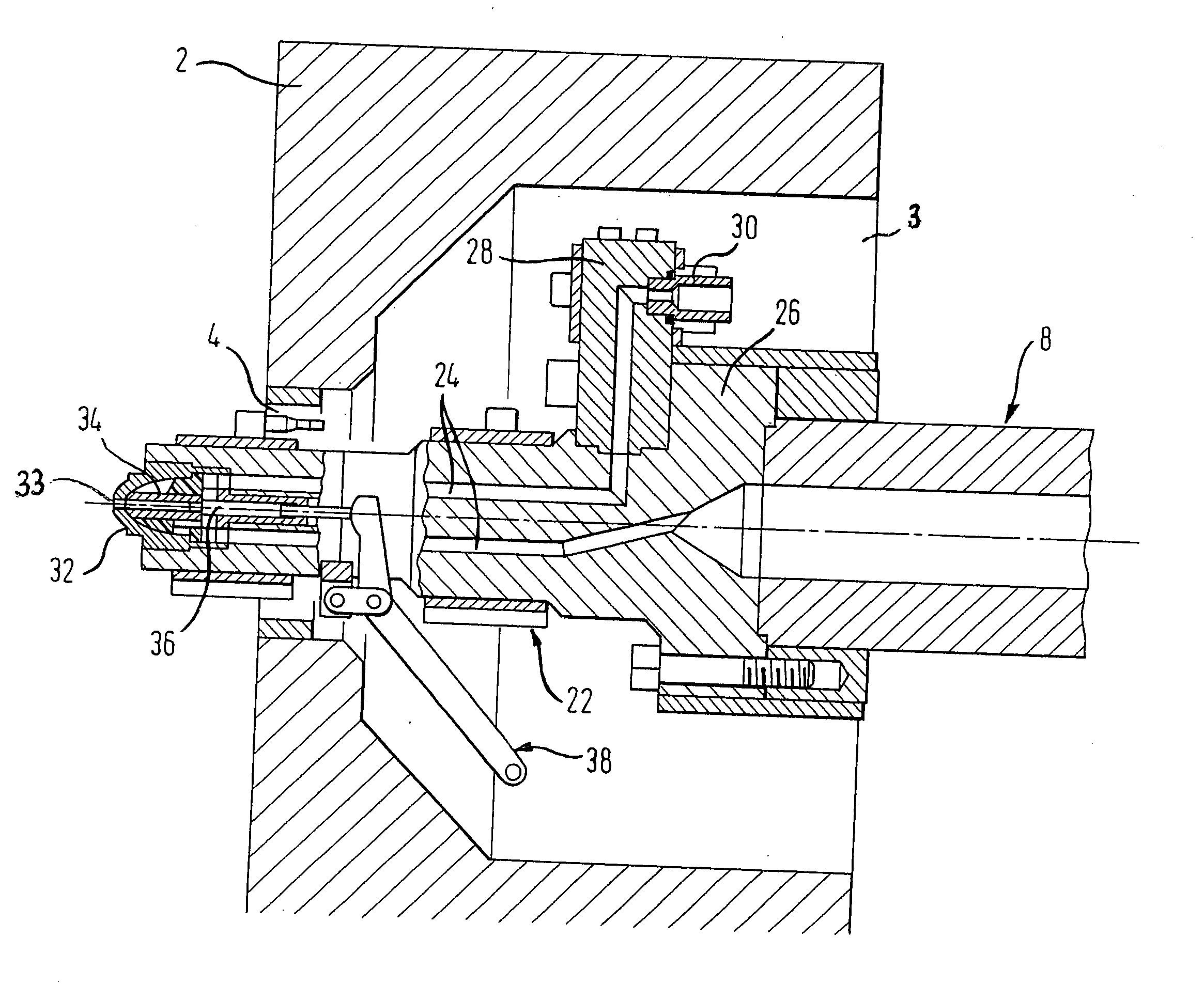
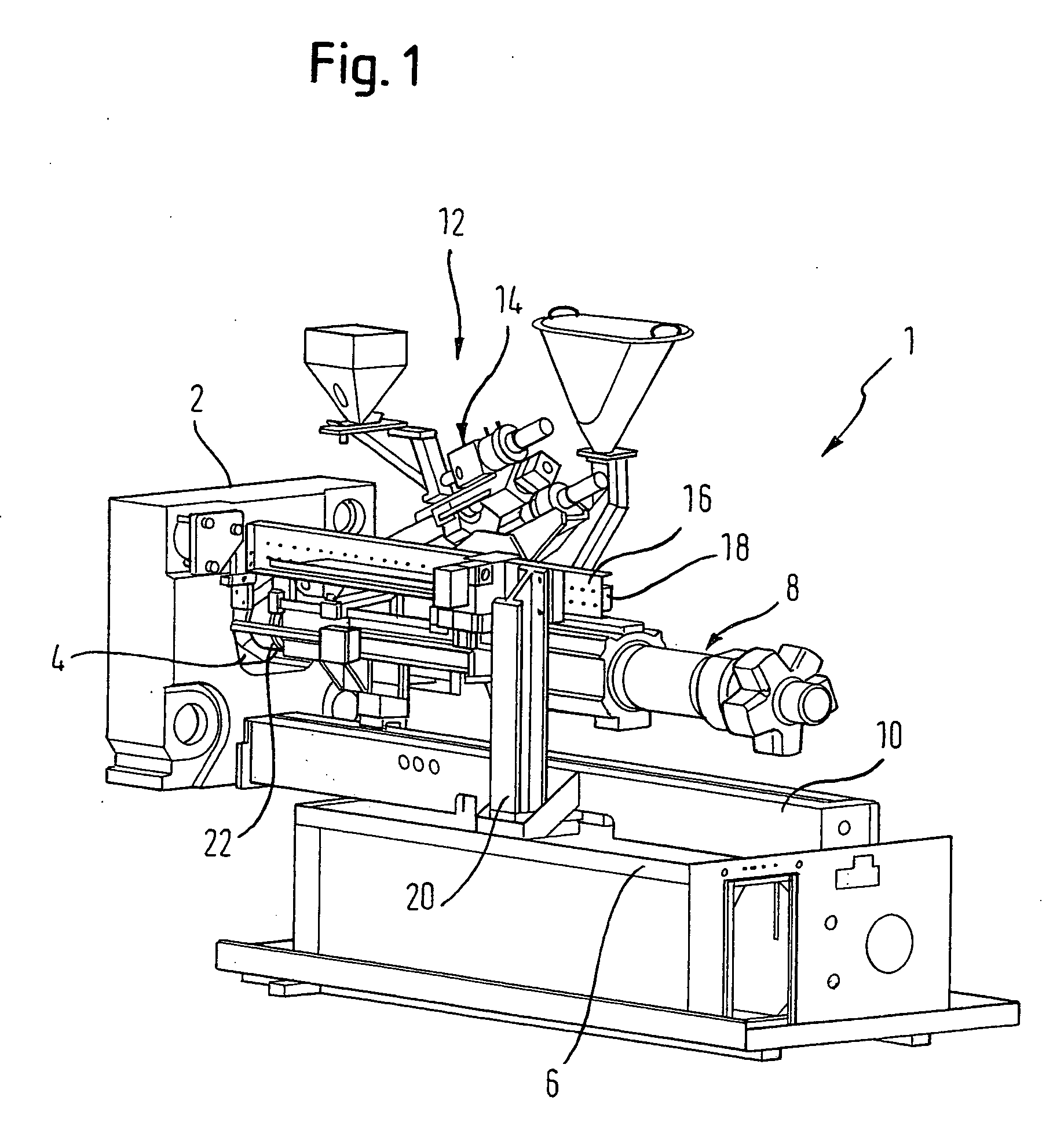
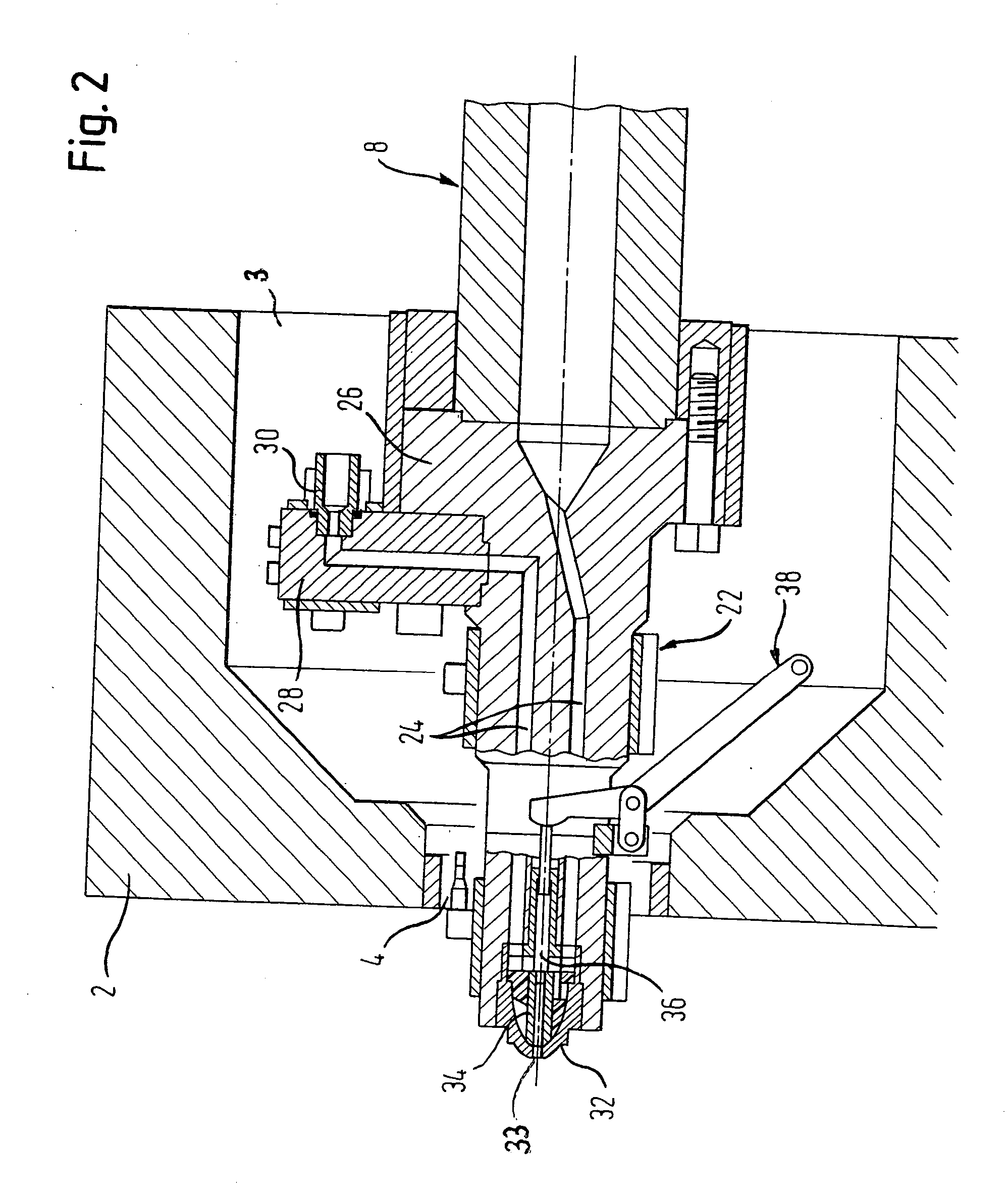
[0038] Throughout all the Figures, same or corresponding elements are generally indicated by same reference numerals. These depicted embodiments are to be understood as illustrative of the invention and not as limiting in any way. It should also be understood that the drawings are not necessarily to scale and that the embodiments are sometimes illustrated by graphic symbols, phantom lines, diagrammatic representations and fragmentary views. In certain instances, details which are not necessary for an understanding of the present invention or which render other details difficult to perceive may have been omitted.

[0039] Turning now to the drawing, and in particular to FIG. 1, there is shown a schematic perspective illustration of an injection side of an injection molding machine, generally designated by reference numeral 1 and retrofitted with a retrofit module according to the present invention, generally designated by reference numeral 12 for adding a plasticizing and injection uni...


PUM

PropertyMeasurementUnit
angleaaaaaaaaaa
angleaaaaaaaaaa
areaaaaaaaaaaa

Abstract

A retrofit module for attachment to an injection molding machine having a plasticizing and injection unit includes a module plasticizing and injection unit, and a support assembly to secure the module plasticizing and injection unit on the injection molding machine independently from the plasticizing and injection unit of the injection molding machine. The module plasticizing and injection unit and the plasticizing and injection unit of the injection molding machine define hereby length axes which extend at an angle of less than 90°. Extending through a nozzle orifice of a platen of the injection molding machine is a nozzle assembly for conducting melt produced by the plasticizing and injection unit of the injection molding machine and the module plasticizing and injection unit. The nozzle assembly is constructed to allow docking of the module plasticizing and injection unit and plasticizing and injection unit of the injection molding machine.

Description

CROSS-REFERENCES TO RELATED APPLICATIONS [0001] This application claims the priority of German Patent Application, Serial No. 10 2004 049 361.8, filed Oct. 8, 2004, pursuant to 35 U.S.C. 119(a)-(d), the subject matter of which is incorporated herein by reference. BACKGROUND OF THE INVENTION [0002] The present invention relates, in general, to an injection molding machine, and more particularly to a retrofit module for adding a plasticizing and injection unit to an injection molding machine. [0003] Nothing in the following discussion of the state of the art is to be construed as an admission of prior art. [0004] Heretofore, standard single-component injection molding machines have been retrofitted to include an additional plasticizing and injection unit by using so-called L and V versions. Hereby, the L version relates to an add-on device which is attached in the horizontal in perpendicular relationship to a major axis of the injection molding machine. Conventionally, an additional m...

Claims


Application Information

Patent Timeline
Patent Type & Authority Applications(United States)
IPC IPC(8): B29C45/20
CPCB29C45/16B29C2045/1685
Inventor SEIDEL, JORGGROTSCH, WILLIBRADA, RALFRAHNHOFER, KLAUS
Owner DEMAG ERGOTECH GMBH
Learn More