
Automatic control method and system for irrigation

a technology of automatic control and irrigation system, applied in the direction of automatic control, process and machine control, ignition, etc., can solve the problems of limited ground water availability, cost of installation and maintenance, and depletion and pollution of existing water reservoirs

Inactive Publication Date: 2005-12-27
UNIV OF FLORIDA RES FOUNDATION INC +1
View PDF14 Cites 89 Cited by
  • Summary
  • Abstract
  • Description
  • Claims
  • Application Information

AI Technical Summary

Benefits of technology

The invention is a controlled irrigation system that uses sensors to measure soil moisture and a control device to determine when to irrigate. The system includes multiple sensors placed at different depths in the soil, and a data store to record data from the sensors. The system also includes an actuator to control water flow and a data logger to interface with the sensors. The method involves measuring soil moisture content, setting thresholds, and irrigating based on the measurements. The technical effect is a more efficient and precise irrigation system that saves water and reduces energy costs.

Problems solved by technology

This concern is fueled by frequent uncontrolled use of available water, which can lead to depletion and pollution of existing water reservoirs.
Further exacerbating these concerns is the fact that in many regions of the world, the availability of ground water is limited.
Nevertheless, due to the high cost of installation and maintenance of water measurement and irrigation systems, suitable irrigation systems frequently go unused.
For example, in some regions rainfall is not uniform with respect to both the months in which the rainfall occurs and the distribution of the rainfall throughout the region.
While some regions experience periods of high rainfall, the amount of rainfall, and therefore fresh water received by a region, remains an important issue, especially in light of demands placed upon water supplies by large populations, high evapotranspiration, and the loss of water through sandy soils with low water holding capacity.

Method used


Image

  • Automatic control method and system for irrigation
  • Automatic control method and system for irrigation
  • Automatic control method and system for irrigation

Examples


Embodiment Construction

[0017]The invention disclosed herein provides a method and system for controlling the irrigation of soil. The present invention can determine whether to induce irrigation of the soil based on the soil moisture content. Thus, the system provides an automated irrigation response that does not rely on human intervention.

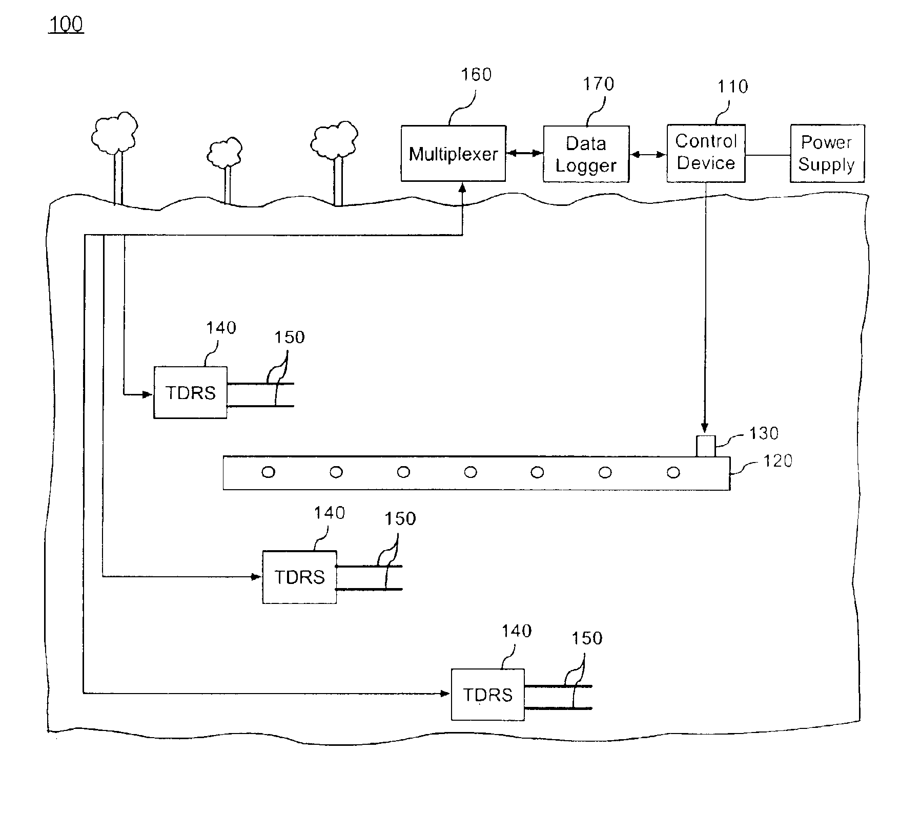
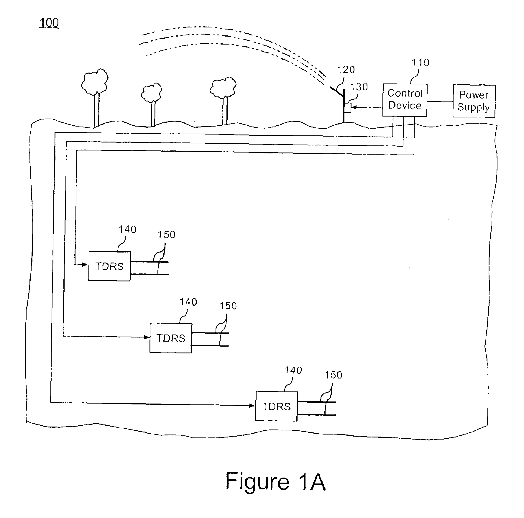
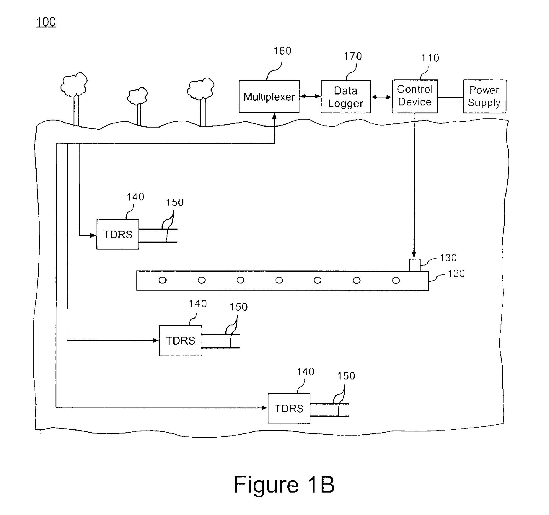
[0018]FIG. 1A is a schematic diagram illustrating an exemplary controlled irrigation system 100. As shown, the irrigation system 100 can include a control device 110, an irrigation structure 120 with an actuator 130, and at least one time domain reflectometry sensor 140 (“TDRS”).

[0019]The TDRS 140 can measure soil moisture which can serve as an indicator whether the soil should be irrigated, as determined by the control device 110. Measurements with TDRS 140 are beneficial as such measurements are nondestructive and offer excellent accuracy and precision. The TDRS 140 can include a plurality of probes 150 which can be used to measure the travel time of an electrical pul...


PUM


Abstract

A controlled irrigation system can include a control device for determining whether to irrigate soil and at least one irrigation structure having an actuator for controlling water flow. The actuator can be communicably coupled to the control device for delivering water to irrigate a region. The controlled irrigation system further can include at least one time domain reflectometry sensor (“TDRS”) located in the soil and communicably coupled to the control device for measuring soil moisture where the control device determines whether to irrigate the soil based on data from the at least one TDRS. Additionally, a method for controlling an irrigation system can include providing multiple TDRS's having probes, distributing each TDRS at a different soil depth, measuring soil moisture content, and irrigating soil based on the measuring step.

Description

CROSS REFERENCE TO RELATED APPLICATIONS[0001]This application claims priority to Provisional Patent Application Ser. No. 60 / 382,323 filed in the U.S. Patent and Trademark Office on May 22, 2002.BACKGROUND OF THE INVENTION[0002]1. Technical Field[0003]The present invention relates to irrigation systems and, more particularly, to controlled irrigation systems.[0004]2. Description of the Related Art[0005]On a global level, the concern over efficient usage of fresh water increases daily. This concern is fueled by frequent uncontrolled use of available water, which can lead to depletion and pollution of existing water reservoirs. Further exacerbating these concerns is the fact that in many regions of the world, the availability of ground water is limited.[0006]Irrigation technology seeks to provide sufficient water resources for efficient agricultural production at high volumes. In other words, irrigation technology attempts to supply the amount of water needed for optimum crop developme...

Claims


Application Information

Patent Timeline
Patent Type & Authority Patents(United States)
IPC IPC(8): A01G25/16G05D22/02
CPCA01G25/167G05D22/02Y10T137/0318Y10T137/189
Inventor DUKES, MICHAEL D.NOGUEIRA, LUIS CARLOSCORNEJO, CAMILOMILLER, LARRY WAYNEHAMAN, DOROTA ZOFIASCHOLBERG, JOHAN M.
Owner UNIV OF FLORIDA RES FOUNDATION INC
Learn More